Manual 26166V1
MicroNet Simplex & MicroNet Plus
Woodward
93
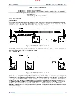
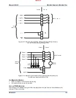
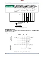
Figure 8-9. Relay Output Interface Wiring to a 24/12 Discrete FTM
Configuration Note
Verify that each set of relay contacts meets the power requirements of the circuit with which it is being
used. Interposing relays are required when the interfaced circuit demands relay contacts with a higher
power rating. If interposing relays or other inductive loads are required, it is recommended that
interposing relays with surge (inductive kickback) protection be used. Improper connection could cause
serious equipment damage.
8.2.3—FTM Reference
See Chapter 13 for detailed wiring of FTMs. See Appendix A for part number Cross Reference for
modules, FTMs, and cables.
8.2.4—Troubleshooting
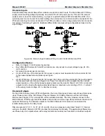
Fault Detection (Module Hardware)
Each MicroNet Discrete I/O Smart-Plus module has a red Fault LED that is turned on when the system is
reset. During initialization of a MicroNet Discrete I/O Smart-Plus module, which occurs after every CPU
reset, the CPU turns the Fault LED on. The CPU then tests each MicroNet Discrete I/O Smart-Plus
module using diagnostic routines built into the software. If the diagnostic test is not passed, the Fault LED
remains on or blinks. If the test is successful, the Fault LED goes off and the RUN LED. If the Fault LED
on a MicroNet Discrete I/O Smart-Plus module is illuminated after the diagnostics and initialization have
been run, the module may be faulty or may be located in the wrong slot.
Released


