Manual 26518V2
5009FT Installation/Hardware
Woodward
8
Chapter 2.
Hardware Description
Introduction
The 5009FT digital control system can be provided in a number of hardware configurations; with different
power supply configurations with or without a 17” Touchscreen PanelPC CCT (Configuration and
Commissioning Tool). An optional 17” PanelPC Operator Interface IFIX Touchscreen HMI is available.
Because this manual addresses all configurations, many of the following hardware descriptions may not
apply to your 5009FT system. Refer to Table 2-1,
Appendix A
for a complete listing of standard and
optional system components.
The system is shipped disassembled and must be installed in a metal cabinet as dictated in 26167V2.
After a control system is received, each item must be located and installed via this manual’s instructions
and
Appendix A
. Precautions to eliminate Electrostatic Discharge must be followed any time parts are
handled or entering the cabinet containing the MicroNet system.
This manual will reference the Woodward MicroNet TMR manual 26167 Volumes 1 and 2. The 5009FT is
a derivative of the MicroNet TMR, and the only difference is that the 5009FT is a pre-configured MicroNet
TMR System.
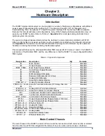
Table 2-1. System Components
Designation Description
Qty
Remarks
U1 Main
chassis
1 Standard
U2 Power
Chassis
1 Standard
PSM1, PSM2
Main Power Supply Module
2
Standard
A1
Kernel Power Supply Module
3
Standard
A2 CPU
Module
3 Standard
A3
MPU & Analog I/O Module
3
Standard
A4
Discrete I/O Module (24 In/12 Out)
3
Standard
A5
Analog HD I/O Module
3
Optional
A6 Actuator
Controller
Module
2 Optional
FTM103-1, 2
Analog Termination Module
2
Standard
FTM104.1A, 1B, 2A,
2B
Discrete Termination Module (F/T Relay–Discrete
In)
4 Standard
FTM105-1, -2
Analog HD I/O Termination Module
2
Optional
FTM106-1, -2
Actuator Controller Termination Module
2
Optional
CCT
Touchscreen PanelPC with Toolkit Software
1
Optional
HMI
Touchscreen PanelPC with IFIX Software
1
Optional
ETH1, ETH2
Hirschmann 8-Port Ethernet Switch
2
Standard
W101-1
Power Chassis to Main Chassis Cable (1 ft/30 cm)
1
Standard
W101-2
Power Chassis to Main Chassis Cable
1
Standard
W102-A, -B, -C
Ethernet Cable (7’)
6
Standard
W103-A, -B, -C
Analog I/O Cable
6
Standard
W104-A, -B, -C
Discrete I/O Cable
6
Standard
W104-1AB, -2AB FTM to FTM Cable (6”/15 cm)
6
Standard
W105-A, -B, -C
Analog Cable
6
Optional
W106-A, -B
Actuator Controller Cable
2
Optional
W107-1, -2
Ethernet Cable (10’)
2
Standard
Main Control Chassis
The main chassis of the 5009FT consists of three six-slot kernel sections. Each kernel section is isolated
from the other two. With this configuration the failure of any one section will not cause a shutdown.
Released
Summary of Contents for MicroNet TMR 5009FT
Page 65: ...Manual 26518V2 5009FT Installation Hardware Woodward 63 Figure 8 4 DSLC Control Released...
Page 67: ...Manual 26518V2 5009FT Installation Hardware Woodward 65 Figure 8 5 Real Power Sensor Released...
Page 70: ...Manual 26518V2 5009FT Installation Hardware Woodward 68 Released...
Page 71: ...Manual 26518V2 5009FT Installation Hardware Woodward 69 Released...
Page 72: ...Manual 26518V2 5009FT Installation Hardware Woodward 70 Released...
Page 73: ...Manual 26518V2 5009FT Installation Hardware Woodward 71 Released...
Page 74: ...Manual 26518V2 5009FT Installation Hardware Woodward 72 Released...
Page 75: ...Manual 26518V2 5009FT Installation Hardware Woodward 73 Released...
Page 76: ...Manual 26518V2 5009FT Installation Hardware Woodward 74 Released...
Page 77: ...Manual 26518V2 5009FT Installation Hardware Woodward 75 Released...
Page 78: ...Manual 26518V2 5009FT Installation Hardware Woodward 76 Released...
Page 79: ...Manual 26518V2 5009FT Installation Hardware Woodward 77 Released...
Page 80: ...Manual 26518V2 5009FT Installation Hardware Woodward 78 Released...
Page 81: ...Manual 26518V2 5009FT Installation Hardware Woodward 79 Released...
Page 82: ...Manual 26518V2 5009FT Installation Hardware Woodward 80 Released...
Page 83: ...Manual 26518V2 5009FT Installation Hardware Woodward 81 Released...
Page 84: ...Manual 26518V2 5009FT Installation Hardware Woodward 82 Released...
Page 85: ...Manual 26518V2 5009FT Installation Hardware Woodward 83 Released...
Page 86: ...Manual 26518V2 5009FT Installation Hardware Woodward 84 Released...
Page 87: ...Manual 26518V2 5009FT Installation Hardware Woodward 85 Released...
Page 88: ...Manual 26518V2 5009FT Installation Hardware Woodward 86 Released...
Page 90: ...Manual 26518V2 5009FT Installation Hardware Woodward 88 Released...
Page 91: ...Manual 26518V2 5009FT Installation Hardware Woodward 89 Released...
Page 92: ...Manual 26518V2 5009FT Installation Hardware Woodward 90 Released...
Page 94: ...Manual 26518V2 5009FT Installation Hardware Woodward 92 Declarations Released...

