Manual 26518V2
5009FT Installation/Hardware
Woodward
9
Each kernel section includes a kernel power supply, a CPU, an analog combo I/O module, and a discrete
I/O module. Optionally an integrating actuator module (Position Controller) and/or a High Density Analog
I/O module may be included. Slot-to-slot logic and power connections are made through an etched-circuit
motherboard located on the back of the chassis. The motherboard and modules are all VERSA module
Eurocard (VME) type. I/O connections are made through cables from the front of the modules to
termination modules in the cabinet. See
Appendix A
for an overview of the main chassis, control
modules, and termination modules.
From a module connector standpoint, any I/O module can be installed in any of the chassis slots
designated for I/O modules. However, when the application software is designed, each module is
assigned to a specific slot, thus the software expects each specific I/O module to always be in its
designated slot.
The 5009FT control chassis is cooled by forced air. In order not to starve modules of air flow, either a
module or a blank module must be installed and secured in each slot. Cooling fans are located on the top
of the main chassis; with one fan per 6-slot card rack. The power supply chassis contains two cooling
fans: one on top and one on the bottom of the chassis. These fans run any time the 5009FT chassis is
powered up.
See Woodward MicroNet TMR manual
26167
Volume 1, Chapter 3, Section 1 for more details on the
Main Chassis.
System Power Supplies (PSM1 and PSM2)
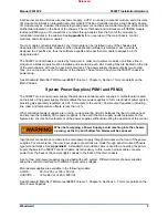
The 5009FT main control power supply chassis uses redundant power supplies. A motherboard located
on the back of the power supply chassis allows the two power supplies to form a redundant power system
providing six separately regulated 24 Vdc, 6 A outputs to the control. Power output regulation, including
line, load, and temperature effects, is less than +5%.
When redundant power supplies are running, current-sharing circuitry balances the load to reduce heat
and improve the reliability of the power supplies. In the event that one supply needs replacement, this
feature also ensures hot replacement of the power supplies without disrupting the operation of the control.
When hot swapping a Power Supply, avoid reaching into the chassis
opening, as the top and bottom fan blades will be exposed.
Input power connections are made to the main power supply through terminals on the front of the power
supplies. For convenience, the user input power connections are made through panel mounted Phoenix
type terminal blocks. See
Appendix B
. A standard 50-pin ribbon cable is used for connecting the power
supply chassis to the 5009FT control chassis. As redundancy to this, a wire harness cable connects
power from the back of the power supply chassis to the back of the main chassis.
A set of two main power supplies are provided with each system. Different models of power supplies
allow the control to interface with different input source voltages.
Main power supplies are available in the following models:
AC/DC –
88–132 Vac or 100–150 Vdc
HVAC/DC –
180–264 Vac or 200–300 Vdc
See Woodward MicroNet TMR manual
26167
Volume 1, Chapter 4, Sections 1–3 for more details on the
Main Power Supplies.
Released
Summary of Contents for MicroNet TMR 5009FT
Page 65: ...Manual 26518V2 5009FT Installation Hardware Woodward 63 Figure 8 4 DSLC Control Released...
Page 67: ...Manual 26518V2 5009FT Installation Hardware Woodward 65 Figure 8 5 Real Power Sensor Released...
Page 70: ...Manual 26518V2 5009FT Installation Hardware Woodward 68 Released...
Page 71: ...Manual 26518V2 5009FT Installation Hardware Woodward 69 Released...
Page 72: ...Manual 26518V2 5009FT Installation Hardware Woodward 70 Released...
Page 73: ...Manual 26518V2 5009FT Installation Hardware Woodward 71 Released...
Page 74: ...Manual 26518V2 5009FT Installation Hardware Woodward 72 Released...
Page 75: ...Manual 26518V2 5009FT Installation Hardware Woodward 73 Released...
Page 76: ...Manual 26518V2 5009FT Installation Hardware Woodward 74 Released...
Page 77: ...Manual 26518V2 5009FT Installation Hardware Woodward 75 Released...
Page 78: ...Manual 26518V2 5009FT Installation Hardware Woodward 76 Released...
Page 79: ...Manual 26518V2 5009FT Installation Hardware Woodward 77 Released...
Page 80: ...Manual 26518V2 5009FT Installation Hardware Woodward 78 Released...
Page 81: ...Manual 26518V2 5009FT Installation Hardware Woodward 79 Released...
Page 82: ...Manual 26518V2 5009FT Installation Hardware Woodward 80 Released...
Page 83: ...Manual 26518V2 5009FT Installation Hardware Woodward 81 Released...
Page 84: ...Manual 26518V2 5009FT Installation Hardware Woodward 82 Released...
Page 85: ...Manual 26518V2 5009FT Installation Hardware Woodward 83 Released...
Page 86: ...Manual 26518V2 5009FT Installation Hardware Woodward 84 Released...
Page 87: ...Manual 26518V2 5009FT Installation Hardware Woodward 85 Released...
Page 88: ...Manual 26518V2 5009FT Installation Hardware Woodward 86 Released...
Page 90: ...Manual 26518V2 5009FT Installation Hardware Woodward 88 Released...
Page 91: ...Manual 26518V2 5009FT Installation Hardware Woodward 89 Released...
Page 92: ...Manual 26518V2 5009FT Installation Hardware Woodward 90 Released...
Page 94: ...Manual 26518V2 5009FT Installation Hardware Woodward 92 Declarations Released...

