Manual 26518V2
5009FT Installation/Hardware
Woodward
11
There are several connections for power on the FTM, each for a dedicated purpose. There are four +24
Vdc connections available for sourcing 4–20 mA inputs. Each connection is protected with a 0.1 A fuse
(F1-F4). There is a +24/12 Vdc output connection available for powering one proximity sensor. Each of
these connections is protected with a 0.1 A fuse (F5, F6).
Two FTMs are provided and used with each 5009FT control (FTM103-1 and FTM103-2). Refer to
Appendix A
for an overview of modules and FTMs used.
See Woodward MicroNet TMR manual
26167
Volume 2, Chapter 12, Section 2 for more details on the
TMR Analog Combo FTM.
Discrete I/O Module (Kernel A/B/C: A4)
Each 24/12 TMR Discrete I/O module (TMR High Density Discrete module) contains circuitry for twenty-
four (24) discrete inputs and twelve (12) TMR discrete outputs, and provides latent fault detection for
each relay output. Each discrete input may be 24 V, or 125 Vdc. Each relay output provides the option of
using a normally open contact, or a normally closed contact.
See Woodward MicroNet TMR manual
26167
Volume 1, Chapter 7, Section 2 for more details on the
TMR 24/12 TMR Discrete I/O Module.
Discrete Termination Modules (F/T Relay Module)
(FTM104-1A, FTM104-1B, FTM104-2A, FTM104-2B)
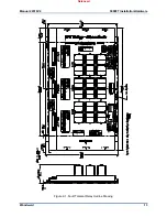
The Fault Tolerant Relay modules are used to connect discrete field wiring to the 5009FT control. Four FT
Relays (FTM104-1A, FTM104-1B, FTM104-2A, and FTM104-2B) are provided and used with each
5009FT control. Refer to
Appendix B
for an overview of FTMs. Each FTM connects to the control’s three
independent Discrete I/O modules through individual cables, and provides a common cage-clamp
terminal connection for customer field wiring. Each FT Relay box contains circuitry for six contact inputs,
three relay outputs and houses circuitry to:
route each contact input signal to the system’s three independent (rack mounted) discrete modules
provide an open / closed contact output based on associated discrete module commands
indicate the health of all relays (latent fault detection)
Discrete input power (contact wetting voltage) can be supplied by the 5009FT control or from an external
source. The 5009FT control provides an isolated 24 Vdc power source for contact wetting. The external
source may be 24 Vdc or 125 Vdc (North American installations only). Separate discrete input terminals
are provided based on the level of contact wetting voltage used. See
Appendix B
.
To comply with CE Marking under the European Low Voltage
Directive (LVD) and CSA requirements, the maximum external circuit
voltage for both the Discrete Inputs and Relay Output circuit are
limited to 18–32 Vdc maximum.
The discrete output relays are mounted on sockets, with 18 relays per FTM. Six relays are used to create
each relay output (normally open and normally closed contacts) and allow latent fault detection. See
Appendix B
. This configuration allows independent testing of each relay output (latent fault detection)
without concern of relay position. Customer power is connected to one side of the configuration and load
to the other.
Discrete outputs can be configured to use latent fault detection to identify output relay failures without
affecting operation. When the contacts are closed, they are periodically opened in pairs, to ensure that they
are in the correct state, and that they change state. When they are open, they are periodically closed
individually, to ensure that they close. Any failures are annunciated, and further testing is disabled.
Released
Summary of Contents for MicroNet TMR 5009FT
Page 65: ...Manual 26518V2 5009FT Installation Hardware Woodward 63 Figure 8 4 DSLC Control Released...
Page 67: ...Manual 26518V2 5009FT Installation Hardware Woodward 65 Figure 8 5 Real Power Sensor Released...
Page 70: ...Manual 26518V2 5009FT Installation Hardware Woodward 68 Released...
Page 71: ...Manual 26518V2 5009FT Installation Hardware Woodward 69 Released...
Page 72: ...Manual 26518V2 5009FT Installation Hardware Woodward 70 Released...
Page 73: ...Manual 26518V2 5009FT Installation Hardware Woodward 71 Released...
Page 74: ...Manual 26518V2 5009FT Installation Hardware Woodward 72 Released...
Page 75: ...Manual 26518V2 5009FT Installation Hardware Woodward 73 Released...
Page 76: ...Manual 26518V2 5009FT Installation Hardware Woodward 74 Released...
Page 77: ...Manual 26518V2 5009FT Installation Hardware Woodward 75 Released...
Page 78: ...Manual 26518V2 5009FT Installation Hardware Woodward 76 Released...
Page 79: ...Manual 26518V2 5009FT Installation Hardware Woodward 77 Released...
Page 80: ...Manual 26518V2 5009FT Installation Hardware Woodward 78 Released...
Page 81: ...Manual 26518V2 5009FT Installation Hardware Woodward 79 Released...
Page 82: ...Manual 26518V2 5009FT Installation Hardware Woodward 80 Released...
Page 83: ...Manual 26518V2 5009FT Installation Hardware Woodward 81 Released...
Page 84: ...Manual 26518V2 5009FT Installation Hardware Woodward 82 Released...
Page 85: ...Manual 26518V2 5009FT Installation Hardware Woodward 83 Released...
Page 86: ...Manual 26518V2 5009FT Installation Hardware Woodward 84 Released...
Page 87: ...Manual 26518V2 5009FT Installation Hardware Woodward 85 Released...
Page 88: ...Manual 26518V2 5009FT Installation Hardware Woodward 86 Released...
Page 90: ...Manual 26518V2 5009FT Installation Hardware Woodward 88 Released...
Page 91: ...Manual 26518V2 5009FT Installation Hardware Woodward 89 Released...
Page 92: ...Manual 26518V2 5009FT Installation Hardware Woodward 90 Released...
Page 94: ...Manual 26518V2 5009FT Installation Hardware Woodward 92 Declarations Released...

