Manual 26518V2
5009FT Installation/Hardware
Woodward
15
Optional Two Channel Actuator Controller Module (Kernel A/B: A6)
Each channel controls an integrating or proportional, hydromechanical or pneumatic actuator. Each
actuator may have up to two position feedback devices. There are several versions available, and the
module part number indicates the module's maximum output current capability. A discrete (gray) cable
must be used with this module. Do not use an analog (black) cable.
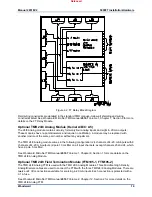
The 2 Channel Actuator Module’s circuitry is divided into two channels. Each channel incorporates an
output current driver and two position resolver feedbacks. Because the 5009FT is a redundant controller,
two actuator drivers from separate modules provide control for each actuator / valve whether wired
separately to dual actuator coils or wired in parallel to a single actuator coil. The redundancy is managed
in the application program and Actuator Module microprocessors so that the two output drivers share load
unless a problem is detected. If one of the drivers goes out of operation, the remaining driver will assume
the required load. When redundant drivers are implemented, only one resolver feedback is available per
channel for direct control. Even though only one position input can be used per channel, the availability of
two channels allows for redundant feedback.
When pilot valves are used, the signal must be connected on the second LVDT input of the card. The
Pilot signal can be redundant, if sent to card A106 and card B106. If physically, only one LVDT signal is
available, the excitation can only be taken from one card, but the signal can be put in parallel.
See Woodward MicroNet TMR manual
26167
Volume 2, Chapter 9, Section 2 for more details on the Two
Channel Actuator Controller Module.
Optional 2-Channel Actuator Field Termination Module (FTM106-1, FTM106-2)
The Two Channel Actuator Controller FTM is used with the 2Ch Actuator Modules. One MicroNet Low
Density Analog cable is used to connect the FTM with the 2Ch Actuator module.
See Woodward MicroNet TMR manual
26167
Volume 2, Chapter 9, Section 2 for more details on the Two
Channel Actuator Controller FTM.
CCT – TouchPanel PC
The 5009FT control system may include an engineering workstation as a Configuration and
Commissioning Tool (CCT) for the control. The software on this device is covered in Volume 3 of this
manual; the hardware used is listed here.
© PHOENIX CONTACT - 2010-01
Phoenix Contact - Valueline Industrial PC
Technical Data
Ambient temperature (operating)
5 to 55 °C
Ambient temperature (storage/transport)
–40 to +70 °C
Permissible humidity (relative)
5 to 95%
Display, 17 in. (dimensions/weight)
452 x 356.5 x 50 mm / 5.85 kg
Degree of protection
IP65 (front), IP20 (back)
Panel Mounting / LED indicators
Power, HDD, Run, Error
Electrical Data
Power supply
nominal 24 Vdc
Power supply
range 19.2—28.8 Vdc
Current draw, typical
1.0—1.5 A
Current draw, maximum
2.0—5.2 A
Power consumption, typical
36.0 W
Power consumption, maximum
124.8 W
RTC battery, typical life
5 years
NOTE: Protective earth ground and circuit ground (return) are connected.
Released
Summary of Contents for MicroNet TMR 5009FT
Page 65: ...Manual 26518V2 5009FT Installation Hardware Woodward 63 Figure 8 4 DSLC Control Released...
Page 67: ...Manual 26518V2 5009FT Installation Hardware Woodward 65 Figure 8 5 Real Power Sensor Released...
Page 70: ...Manual 26518V2 5009FT Installation Hardware Woodward 68 Released...
Page 71: ...Manual 26518V2 5009FT Installation Hardware Woodward 69 Released...
Page 72: ...Manual 26518V2 5009FT Installation Hardware Woodward 70 Released...
Page 73: ...Manual 26518V2 5009FT Installation Hardware Woodward 71 Released...
Page 74: ...Manual 26518V2 5009FT Installation Hardware Woodward 72 Released...
Page 75: ...Manual 26518V2 5009FT Installation Hardware Woodward 73 Released...
Page 76: ...Manual 26518V2 5009FT Installation Hardware Woodward 74 Released...
Page 77: ...Manual 26518V2 5009FT Installation Hardware Woodward 75 Released...
Page 78: ...Manual 26518V2 5009FT Installation Hardware Woodward 76 Released...
Page 79: ...Manual 26518V2 5009FT Installation Hardware Woodward 77 Released...
Page 80: ...Manual 26518V2 5009FT Installation Hardware Woodward 78 Released...
Page 81: ...Manual 26518V2 5009FT Installation Hardware Woodward 79 Released...
Page 82: ...Manual 26518V2 5009FT Installation Hardware Woodward 80 Released...
Page 83: ...Manual 26518V2 5009FT Installation Hardware Woodward 81 Released...
Page 84: ...Manual 26518V2 5009FT Installation Hardware Woodward 82 Released...
Page 85: ...Manual 26518V2 5009FT Installation Hardware Woodward 83 Released...
Page 86: ...Manual 26518V2 5009FT Installation Hardware Woodward 84 Released...
Page 87: ...Manual 26518V2 5009FT Installation Hardware Woodward 85 Released...
Page 88: ...Manual 26518V2 5009FT Installation Hardware Woodward 86 Released...
Page 90: ...Manual 26518V2 5009FT Installation Hardware Woodward 88 Released...
Page 91: ...Manual 26518V2 5009FT Installation Hardware Woodward 89 Released...
Page 92: ...Manual 26518V2 5009FT Installation Hardware Woodward 90 Released...
Page 94: ...Manual 26518V2 5009FT Installation Hardware Woodward 92 Declarations Released...

