Manual 26518V2
5009FT Installation/Hardware
Woodward
21
Each main power supply provides three separate 24 Vdc outputs
rated for 0–6 A each. To preserve system integrity, it is
recommended that the control’s three isolated 24 Vdc outputs be
kept isolated from each other at all times. If the control’s 24 V power
is used to power external devices, the system’s three 24 V outputs
must not be tied together. If these outputs are tied together, and a
short circuit occurs, it will shut down the entire 5009FT control.
External devices requiring 24 Vdc power must be connected to only
one of the power supplies.
Externally powered analog inputs or outputs and external relay coil
power must be supplied by and IEC rated or NFPA 70 (NEC) Class 2
power supply as required by local authority having jurisdiction.
Speed Sensor Inputs—TMR Analog Combo Module
The 5009FT control uses speed sensing probes mounted off of a gear connected or coupled to the
turbine’s rotor to sense turbine rotor speed. The first three channels of the control accept passive
magnetic pickup units (MPUs), 12 Vdc proximity probes or 24 Vdc proximity probes. Channel 4 only
accepts 12 Vdc proximity probes or 24 Vdc proximity probes, as this channel is dedicated to be used for
slow speed detection only.
It is not recommended that gears mounted on an auxiliary shaft coupled to the turbine rotor be used to
sense turbine speed. Auxiliary shafts tend to turn more slowly than the turbine rotor (reducing speed
sensing resolution) and have coupling gear back-lash, which results in less than optimum speed control.
For safety purposes it is also not recommend that the speed sensing device sense speed from a gear
coupled to a generator or mechanical drive side of a system’s rotor coupling.
All speed sensing inputs use the same programmed gear ratio and number of teeth to calculate speed,
thus the speed probes used should sense speed from the same gear. The 5009FT control can sense and
control turbine speed from a single speed probe, however, it is recommended that all applications use
multiple speed probes to increase system reliability.
A passive MPU provides a frequency output signal corresponding to turbine speed by sensing the
movement of a gear’s teeth past the MPU’s pole piece. The closer the MPU’s pole piece is to a gear’s
teeth and the faster the gear turns the higher a passive MPU’s output amplitude will be. The 5009FT
control must sense an MPU voltage of 1 to 25 Vrms for proper operation.
Depending on an MPU’s limitations, each input channel can be jumper configured to allow an MPU to drive
either two or three inputs (some MPUs cannot drive three inputs). Wire jumpers must be installed to allow
an MPU to drive into all three inputs. When the jumpers are not installed, only two input modules are driven
by a MPU. With proper MPU, gear size, and MPU-to-gear clearance, speed measurement should be
capable down to 100 Hz. Standard MPU clearance is recommended to be 0.25 to 1.02 mm (0.010 to 0.040
inch) from tooth face to pole piece. For information on selecting the correct MPU or gear size, please refer
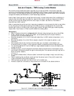
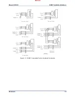
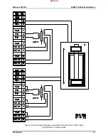
to Woodward manual 82510. See Figure 4-4 for wiring schematic.
Speed channel 4 has to be configured to receive a proximity probe. A proximity probe may be used to sense
very low speeds. With a proximity probe, speed can be sensed down to 0.5 Hz. The 5009FT control can be
programmed to turn on or off a turbine turning gear using a relay output programmed as a slow speed
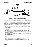
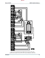
switch. See Figure 4-5 for proximity probe wiring schematic.
Because of differences between the sensing circuits required to interface with passive (MPUs) and active
(proximity) probes, separate terminals are provided for each type. This allows a simple method of field
selecting the type of speed input based on the type of probe used. Short-circuit protected 12 Vdc and 24
Vdc sources, with isolation diodes on the power, common, and output source lines, are provided with
each speed input to power system proximity probes.
Released
Summary of Contents for MicroNet TMR 5009FT
Page 65: ...Manual 26518V2 5009FT Installation Hardware Woodward 63 Figure 8 4 DSLC Control Released...
Page 67: ...Manual 26518V2 5009FT Installation Hardware Woodward 65 Figure 8 5 Real Power Sensor Released...
Page 70: ...Manual 26518V2 5009FT Installation Hardware Woodward 68 Released...
Page 71: ...Manual 26518V2 5009FT Installation Hardware Woodward 69 Released...
Page 72: ...Manual 26518V2 5009FT Installation Hardware Woodward 70 Released...
Page 73: ...Manual 26518V2 5009FT Installation Hardware Woodward 71 Released...
Page 74: ...Manual 26518V2 5009FT Installation Hardware Woodward 72 Released...
Page 75: ...Manual 26518V2 5009FT Installation Hardware Woodward 73 Released...
Page 76: ...Manual 26518V2 5009FT Installation Hardware Woodward 74 Released...
Page 77: ...Manual 26518V2 5009FT Installation Hardware Woodward 75 Released...
Page 78: ...Manual 26518V2 5009FT Installation Hardware Woodward 76 Released...
Page 79: ...Manual 26518V2 5009FT Installation Hardware Woodward 77 Released...
Page 80: ...Manual 26518V2 5009FT Installation Hardware Woodward 78 Released...
Page 81: ...Manual 26518V2 5009FT Installation Hardware Woodward 79 Released...
Page 82: ...Manual 26518V2 5009FT Installation Hardware Woodward 80 Released...
Page 83: ...Manual 26518V2 5009FT Installation Hardware Woodward 81 Released...
Page 84: ...Manual 26518V2 5009FT Installation Hardware Woodward 82 Released...
Page 85: ...Manual 26518V2 5009FT Installation Hardware Woodward 83 Released...
Page 86: ...Manual 26518V2 5009FT Installation Hardware Woodward 84 Released...
Page 87: ...Manual 26518V2 5009FT Installation Hardware Woodward 85 Released...
Page 88: ...Manual 26518V2 5009FT Installation Hardware Woodward 86 Released...
Page 90: ...Manual 26518V2 5009FT Installation Hardware Woodward 88 Released...
Page 91: ...Manual 26518V2 5009FT Installation Hardware Woodward 89 Released...
Page 92: ...Manual 26518V2 5009FT Installation Hardware Woodward 90 Released...
Page 94: ...Manual 26518V2 5009FT Installation Hardware Woodward 92 Declarations Released...

