Manual 26518V2
5009FT Installation/Hardware
Woodward
29
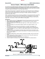
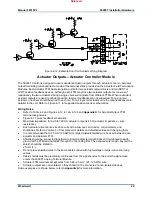
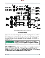
Figure 4-12. Example Dual Coil Actuator Wiring Diagram
Actuator Outputs—Actuator Controller Module
The 5009FT Control is designed to use redundant actuator outputs for each actuator or servo. Actuator
output field wiring terminations are made at the terminal strips provided on the Actuator Field Termination
Modules. Each Actuator FTM has termination points for two actuator output drivers and two RVDT or
LVDT position feedback devices. Although each FTM may drive two actuator outputs, for reasons of
redundancy the two actuators driving a single valve will originate from different FTMs. When redundant
actuator outputs are used, redundant position resolver feedbacks are not supported. For a dual coil
actuator, one driver should be wired to each coil. For a single coil actuator, wire the redundant drivers in
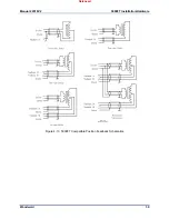
parallel to the coil. Refer to Figure 4-11 for supported position resolver schematics.
Wiring Notes:
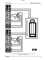
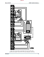
Refer to Table 4-2 and Figures 4-12, 4-12a, 4-12b and
Appendix A
for Actuator Output FTM
terminal assignments.
Figure 4-11 gives feedback schematics.
Maximum impedance for a 20 to 160 mA actuator output is 45
Ω
(actuator imp wire
resistance).
Each actuator driver senses its drive current to allow over- and under- current alarms and
shutdowns. Refer to Volume 3 of this manual for details on defaulted values and changing them.
It is recommended that 0.75 mm² (20 AWG) or larger twisted/shielded wire be used between each
actuator and Actuator FTM.
Shields should be connected together at all intermediate terminal blocks and terminated to earth
ground at the FTM terminal block through the Grounding Bar. The exposed wire length, beyond the
shield, should be limited to
25 mm (1”).
Do not place shielded wires in the same cable conduit with high-voltage or large-current-carrying
cables.
Cable shields must be electrically continuous from the signal source to the point the signal wire
enters the 5009FT Analog Terminal Module.
Actuator FTM terminals accept wires from 0.08–2.5 mm² (27–12 AWG) wire.
Actuator outputs are not isolated, so they should not be connected to non-isolated devices.
Some examples are shown below, refer to
Appendix A
for more information.
Released
Summary of Contents for MicroNet TMR 5009FT
Page 65: ...Manual 26518V2 5009FT Installation Hardware Woodward 63 Figure 8 4 DSLC Control Released...
Page 67: ...Manual 26518V2 5009FT Installation Hardware Woodward 65 Figure 8 5 Real Power Sensor Released...
Page 70: ...Manual 26518V2 5009FT Installation Hardware Woodward 68 Released...
Page 71: ...Manual 26518V2 5009FT Installation Hardware Woodward 69 Released...
Page 72: ...Manual 26518V2 5009FT Installation Hardware Woodward 70 Released...
Page 73: ...Manual 26518V2 5009FT Installation Hardware Woodward 71 Released...
Page 74: ...Manual 26518V2 5009FT Installation Hardware Woodward 72 Released...
Page 75: ...Manual 26518V2 5009FT Installation Hardware Woodward 73 Released...
Page 76: ...Manual 26518V2 5009FT Installation Hardware Woodward 74 Released...
Page 77: ...Manual 26518V2 5009FT Installation Hardware Woodward 75 Released...
Page 78: ...Manual 26518V2 5009FT Installation Hardware Woodward 76 Released...
Page 79: ...Manual 26518V2 5009FT Installation Hardware Woodward 77 Released...
Page 80: ...Manual 26518V2 5009FT Installation Hardware Woodward 78 Released...
Page 81: ...Manual 26518V2 5009FT Installation Hardware Woodward 79 Released...
Page 82: ...Manual 26518V2 5009FT Installation Hardware Woodward 80 Released...
Page 83: ...Manual 26518V2 5009FT Installation Hardware Woodward 81 Released...
Page 84: ...Manual 26518V2 5009FT Installation Hardware Woodward 82 Released...
Page 85: ...Manual 26518V2 5009FT Installation Hardware Woodward 83 Released...
Page 86: ...Manual 26518V2 5009FT Installation Hardware Woodward 84 Released...
Page 87: ...Manual 26518V2 5009FT Installation Hardware Woodward 85 Released...
Page 88: ...Manual 26518V2 5009FT Installation Hardware Woodward 86 Released...
Page 90: ...Manual 26518V2 5009FT Installation Hardware Woodward 88 Released...
Page 91: ...Manual 26518V2 5009FT Installation Hardware Woodward 89 Released...
Page 92: ...Manual 26518V2 5009FT Installation Hardware Woodward 90 Released...
Page 94: ...Manual 26518V2 5009FT Installation Hardware Woodward 92 Declarations Released...

