Manual 26518V2
5009FT Installation/Hardware
Woodward
33
FTM Contact Inputs (F/T Relay–Discrete In)
The 5009FT control accepts 24 contact inputs. Each of the control’s four Discrete Termination Modules
accepts six contact inputs. All 24 contact inputs are configurable, but the first 6 have been defaulted to
functions required by most all systems and should not be changed.
The Preset Contact Inputs are:
External Emergency Shutdown #1 (fixed)
External
Reset
Raise Speed Setpoint
Lower Speed Setpoint
Start
Command
Controlled Stop Sequence
The control will initiate an emergency shutdown any time the External Emergency Shutdown contact input
is opened. This input is typically tied into the system’s trip string. Before starting, the External Emergency
Shutdown input must have an external contact or switch wired to it and it must be closed. The external
reset contact can be used to remotely clear latched alarms and trip conditions. The raise and lower speed
setpoint inputs can be used to remotely raise and lower speed or load.
Applications requiring external contact inputs must have the desired function assigned or configured to a
specific input. Refer to Volume 3 of this manual for a complete list of programmable contact input options.
Normal Contacts must change state for a maximum of 160 milliseconds and a minimum of 80 milliseconds
for the control to sense and register a change in state.
The ESD contact (#1) must change state for a maximum of 20 milliseconds and a minimum of 10
milliseconds for the control to sense and register a change in state.
Contact wetting voltage can be supplied by the control or from an external source. 24 Vdc contact wetting
voltage is available on each FTM (with isolation diodes on the power and common lines). Optionally, an
external 18–32 Vdc power source or an external 100–150 Vdc power source can be used to source the
circuit wetting voltage. (The FTM’s CE and CSA markings only apply to the 24 V option.) Because all
discrete inputs are fully isolated, a common reference point must be established between the input opto-
isolators and the contact wetting power source. If the 24 Vdc internal power source is used as for contact
wetting, jumpers are required between FTM terminals 33 & 34, and terminals 33 & 35. If an external power
source is used for contact wetting, the external source’s common must be connected to the FTM’s discrete
input commons (terminals 34 & 35).
HIGH VOLTAGE—If high voltage discrete inputs are used, and there
is 125 Vdc on the FTM terminal blocks, there will be 125 Vdc on the
FTM cables and cable connectors. All modules should be installed
and cables connected before wiring the FTM.
Wiring Notes:
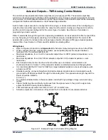
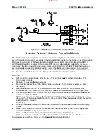
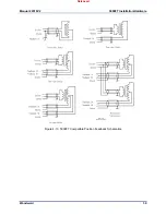
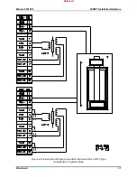
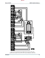
Refer to Figures 4-26 through 4-28 and
Appendix A
for Contact Input wiring connections to the
FTMs.
The wiring information on DI’s in section 7.1 of 26167V1 must be followed.
All contact inputs accept dry contacts.
The internal 24 Vdc power source, an external 18–36 Vdc power source or an external 100–150 Vdc
power source can be used for circuit wetting. (The FTM’s European CE Compliance and CSA
requirements only apply to the 24 V option.)
If the 24 Vdc internal power source is used as for contact wetting, jumpers are required between
FTM terminals 33 & 34 and terminals 33 & 35.
Released
Summary of Contents for MicroNet TMR 5009FT
Page 65: ...Manual 26518V2 5009FT Installation Hardware Woodward 63 Figure 8 4 DSLC Control Released...
Page 67: ...Manual 26518V2 5009FT Installation Hardware Woodward 65 Figure 8 5 Real Power Sensor Released...
Page 70: ...Manual 26518V2 5009FT Installation Hardware Woodward 68 Released...
Page 71: ...Manual 26518V2 5009FT Installation Hardware Woodward 69 Released...
Page 72: ...Manual 26518V2 5009FT Installation Hardware Woodward 70 Released...
Page 73: ...Manual 26518V2 5009FT Installation Hardware Woodward 71 Released...
Page 74: ...Manual 26518V2 5009FT Installation Hardware Woodward 72 Released...
Page 75: ...Manual 26518V2 5009FT Installation Hardware Woodward 73 Released...
Page 76: ...Manual 26518V2 5009FT Installation Hardware Woodward 74 Released...
Page 77: ...Manual 26518V2 5009FT Installation Hardware Woodward 75 Released...
Page 78: ...Manual 26518V2 5009FT Installation Hardware Woodward 76 Released...
Page 79: ...Manual 26518V2 5009FT Installation Hardware Woodward 77 Released...
Page 80: ...Manual 26518V2 5009FT Installation Hardware Woodward 78 Released...
Page 81: ...Manual 26518V2 5009FT Installation Hardware Woodward 79 Released...
Page 82: ...Manual 26518V2 5009FT Installation Hardware Woodward 80 Released...
Page 83: ...Manual 26518V2 5009FT Installation Hardware Woodward 81 Released...
Page 84: ...Manual 26518V2 5009FT Installation Hardware Woodward 82 Released...
Page 85: ...Manual 26518V2 5009FT Installation Hardware Woodward 83 Released...
Page 86: ...Manual 26518V2 5009FT Installation Hardware Woodward 84 Released...
Page 87: ...Manual 26518V2 5009FT Installation Hardware Woodward 85 Released...
Page 88: ...Manual 26518V2 5009FT Installation Hardware Woodward 86 Released...
Page 90: ...Manual 26518V2 5009FT Installation Hardware Woodward 88 Released...
Page 91: ...Manual 26518V2 5009FT Installation Hardware Woodward 89 Released...
Page 92: ...Manual 26518V2 5009FT Installation Hardware Woodward 90 Released...
Page 94: ...Manual 26518V2 5009FT Installation Hardware Woodward 92 Declarations Released...


