Manual 26518V2
5009FT Installation/Hardware
Woodward
35
When a relay output is open, the contacts of all six relays are open. Because of the series-parallel
configuration that the relays are in, the failure of any one relay will not cause the output to be closed. The
relay output would continue to be open. Once a relay output is open, the output’s individual relays are
periodically closed and re-opened one by one, to ensure that they were in the correct state, and that they
change state. Position readback circuitry allows the state of each relay contact to be detected. Any failures
are annunciated, and further testing is disabled without affecting the state of the relay output contact or
control operation.
Latent fault detection (LFD) is not usable with all applications or circuits. The control’s LFD logic can only
work with circuits using voltages between 18–32 Vdc, 100–150 Vdc, or 88–132 Vac. For LFD to work, a
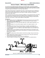
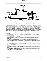
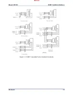
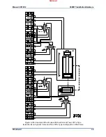
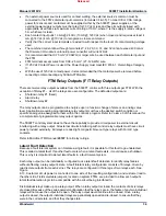
small leakage current is passed through the circuit’s load. See Figures 4-11, 4-12, and 4-13. Depending
on the size of the load, the leakage current may be enough to cause a load to be on or active, when a
relay contact is open. In this case, the individual relay’s LFD logic may be disabled, eliminating the
leakage current.
If LFD is desired, but the leakage current is too great for the load, an external resistor may be connected
in parallel with the circuit’s load to shunt some of the leakage current away from the load. To prevent
failure of a load to de-energize, careful consideration should be given, to ensure that the voltage
developed across the load due to leakage current is below the load’s drop-out voltage.
With LFD, when a relay contact is closed, no difference in operation is experienced; the relay output
appears as a closed contact. However, when a relay contact is open, it appears to the interfaced circuit
as a large resistor instead of an open contact. Thus a small amount of current is leaked to the load,
resulting in a developed voltage across the load. In most cases this has no bearing on the customer’s
circuitry, because such a small amount of voltage is developed across its load. However, when a relay
output is used with a very high resistance load (low current load), enough voltage may be developed
across the load to prevent it from de-energizing.
To verify if Latent Fault Detection can be used with a relay output:
1. Verify that circuit the relay output is used with has a voltage level of 18–32 Vdc, 100–150 Vdc, or 88–
132 Vac. If circuit voltage is not within these ranges, disable the relay output’s latent fault detection by
placing the relay jumpers in their disable state. See Figure 4-17.
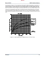
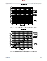
2. Use the graph below (Figures 4-12, 4-13, or 4-14) which corresponds to the circuit’s voltage level to
determine if the voltage developed across the load (due to the leakage current) is lower than the
load’s drop-out voltage level.
Acquire the resistance of the load (relay, motor, solenoid, etc.) to be driven by the relay.
Acquire the load’s minimum drop-out voltage.
From the bottom of the graph, follow the line corresponding to the load’s resistance, up until it
intersects the circuit power line. At this point the corresponding voltage level (on the left of the
graph) is the level of voltage that will be developed across the load due to leakage current.
3. If the developed load voltage (from the graph) is less than the load’s drop-out voltage, latent fault
detection can be used with the circuit.
4. If the developed load voltage is greater than the load’s drop-out voltage, it is recommended that latent
fault detection be disabled, or that a resistor be connected in parallel (shunt) with the load. A correctly
sized resistor connected in parallel with the circuit load will decrease the developed load voltage
below the load’s drop-out voltage level. Using the corresponding LFD graph and the load’s minimum
drop-out voltage, perform the above procedure in reverse (See step #2) to determine an acceptable
shunt resistance. When selecting a shunt resistor also verify that its voltage and wattage ratings meet
that of the circuit.
LFD Verification Example:
Circuit Power = 110 Vac
Load Resistance = 200
Ω
Load drop-out voltage = 25 Vac
Released
Summary of Contents for MicroNet TMR 5009FT
Page 65: ...Manual 26518V2 5009FT Installation Hardware Woodward 63 Figure 8 4 DSLC Control Released...
Page 67: ...Manual 26518V2 5009FT Installation Hardware Woodward 65 Figure 8 5 Real Power Sensor Released...
Page 70: ...Manual 26518V2 5009FT Installation Hardware Woodward 68 Released...
Page 71: ...Manual 26518V2 5009FT Installation Hardware Woodward 69 Released...
Page 72: ...Manual 26518V2 5009FT Installation Hardware Woodward 70 Released...
Page 73: ...Manual 26518V2 5009FT Installation Hardware Woodward 71 Released...
Page 74: ...Manual 26518V2 5009FT Installation Hardware Woodward 72 Released...
Page 75: ...Manual 26518V2 5009FT Installation Hardware Woodward 73 Released...
Page 76: ...Manual 26518V2 5009FT Installation Hardware Woodward 74 Released...
Page 77: ...Manual 26518V2 5009FT Installation Hardware Woodward 75 Released...
Page 78: ...Manual 26518V2 5009FT Installation Hardware Woodward 76 Released...
Page 79: ...Manual 26518V2 5009FT Installation Hardware Woodward 77 Released...
Page 80: ...Manual 26518V2 5009FT Installation Hardware Woodward 78 Released...
Page 81: ...Manual 26518V2 5009FT Installation Hardware Woodward 79 Released...
Page 82: ...Manual 26518V2 5009FT Installation Hardware Woodward 80 Released...
Page 83: ...Manual 26518V2 5009FT Installation Hardware Woodward 81 Released...
Page 84: ...Manual 26518V2 5009FT Installation Hardware Woodward 82 Released...
Page 85: ...Manual 26518V2 5009FT Installation Hardware Woodward 83 Released...
Page 86: ...Manual 26518V2 5009FT Installation Hardware Woodward 84 Released...
Page 87: ...Manual 26518V2 5009FT Installation Hardware Woodward 85 Released...
Page 88: ...Manual 26518V2 5009FT Installation Hardware Woodward 86 Released...
Page 90: ...Manual 26518V2 5009FT Installation Hardware Woodward 88 Released...
Page 91: ...Manual 26518V2 5009FT Installation Hardware Woodward 89 Released...
Page 92: ...Manual 26518V2 5009FT Installation Hardware Woodward 90 Released...
Page 94: ...Manual 26518V2 5009FT Installation Hardware Woodward 92 Declarations Released...


