Manual 26518V2
5009FT Installation/Hardware
Woodward
42
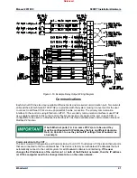
Port configurations:
CPU-A (RS-232/422/485) can function as a port on Modbus #1 or #2
CPU-B (RS-232/422/485) can function as a port on Modbus #1 or #2
CPU-C (RS-232/422/485) can function as a port on Modbus #1 or #2
All communication ports can interface with other devices via RS-232 communication. RS-232 communication
is limited to a distance of 15 m (50 ft). In cases where a device which is being interfaced to is located a
distance of greater than 15 m (50 ft) from the control, it is recommended to use RS-422 or RS-485. RS-422
and RS-485 communication support multi-dropping (multiple slaves on a single communication line); RS-
232 communication does not.
The 5009FT control can simultaneously communicate with up to five Modbus based devices using ASCII
or RTU Modbus transmission protocols. The Ethernet Modbus links can be configured for TCP or UDP
protocol. Refer to Volume 3 of this manual for a list of all the Modbus commands and parameters
available.
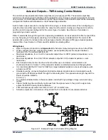
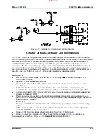
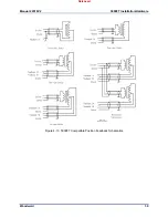
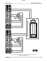
Control Wiring Diagrams
When installing a system, follow all I/O specific wiring notes (covered earlier in this chapter) and general
wiring notes below. For ease of identification system notes are displayed within a triangle on each wiring
diagram. The number that appears in a triangle pertains to a wiring note.
Appendix A
provides all
necessary information to wire to the system.
Wiring Notes
1 Refer
to
Appendix A
.
2 Refer to MicroNet TMR manual
26167
for input power ratings.
3 Consult the Customer supplied wiring.
4 Optional Wiring (dependent upon system options).
5 Read and follow all Wiring notes, instructions, and recommendations within this chapter when
electrically installing a system.
6 Confirm each connection before operating unit.
7 All analog inputs must be isolated from earth ground.
8 Follow authorized standards for conduit loading and sealing.
9 All wires to terminal blocks shall have wire markers, marked with associated terminal number.
System Power-Up
If at any time during this procedure the defined or expected result is not achieved, step to Chapter 5 of
this volume and begin system troubleshooting.
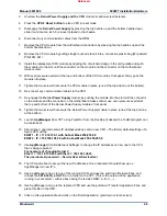
1. Turn the power for one power supply on and verify that the power supply’s green LED is the only
power supply LED on.
2. Turn the power for second power supply on and verify that the power supply’s green LED is the only
power supply LED on.
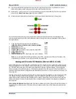
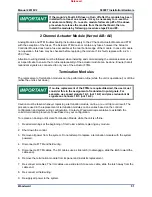
At this point, the system will perform off-line diagnostics, this diagnostics testing will typically take about
2
minutes
. When all CPUs have synchronized and completed their diagnostic tests, no red LEDs should be
on, and the control will begin running the application program.
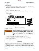
When the momentary RESET button is pressed the CPU’s red Fault
and Watchdog LEDs should go out and the green RUN LED should
go on. At this time, the CPU is performing the self-diagnostics and
boot-up processes. If only one CPU has been reset, (other CPUs still
failed) the 5009FT will wait for another CPU to boot-up before both
CPUs will go to a running state.
Released
Summary of Contents for MicroNet TMR 5009FT
Page 65: ...Manual 26518V2 5009FT Installation Hardware Woodward 63 Figure 8 4 DSLC Control Released...
Page 67: ...Manual 26518V2 5009FT Installation Hardware Woodward 65 Figure 8 5 Real Power Sensor Released...
Page 70: ...Manual 26518V2 5009FT Installation Hardware Woodward 68 Released...
Page 71: ...Manual 26518V2 5009FT Installation Hardware Woodward 69 Released...
Page 72: ...Manual 26518V2 5009FT Installation Hardware Woodward 70 Released...
Page 73: ...Manual 26518V2 5009FT Installation Hardware Woodward 71 Released...
Page 74: ...Manual 26518V2 5009FT Installation Hardware Woodward 72 Released...
Page 75: ...Manual 26518V2 5009FT Installation Hardware Woodward 73 Released...
Page 76: ...Manual 26518V2 5009FT Installation Hardware Woodward 74 Released...
Page 77: ...Manual 26518V2 5009FT Installation Hardware Woodward 75 Released...
Page 78: ...Manual 26518V2 5009FT Installation Hardware Woodward 76 Released...
Page 79: ...Manual 26518V2 5009FT Installation Hardware Woodward 77 Released...
Page 80: ...Manual 26518V2 5009FT Installation Hardware Woodward 78 Released...
Page 81: ...Manual 26518V2 5009FT Installation Hardware Woodward 79 Released...
Page 82: ...Manual 26518V2 5009FT Installation Hardware Woodward 80 Released...
Page 83: ...Manual 26518V2 5009FT Installation Hardware Woodward 81 Released...
Page 84: ...Manual 26518V2 5009FT Installation Hardware Woodward 82 Released...
Page 85: ...Manual 26518V2 5009FT Installation Hardware Woodward 83 Released...
Page 86: ...Manual 26518V2 5009FT Installation Hardware Woodward 84 Released...
Page 87: ...Manual 26518V2 5009FT Installation Hardware Woodward 85 Released...
Page 88: ...Manual 26518V2 5009FT Installation Hardware Woodward 86 Released...
Page 90: ...Manual 26518V2 5009FT Installation Hardware Woodward 88 Released...
Page 91: ...Manual 26518V2 5009FT Installation Hardware Woodward 89 Released...
Page 92: ...Manual 26518V2 5009FT Installation Hardware Woodward 90 Released...
Page 94: ...Manual 26518V2 5009FT Installation Hardware Woodward 92 Declarations Released...

