Manual 26518V2
5009FT Installation/Hardware
Woodward
49
22. The CPU will Start the application and synchronize with the other kernels. It will obtain all current
states and tunable values during synchronization with the other Kernels.
23. At this point – return to the CCT (re-connect if Kernel A was the area affect by the above procedure)
and go to the
Alarm Summary
page and enter a RESET.
24. All kernel and module alarms should clear, restoring complete fault tolerance to the system.
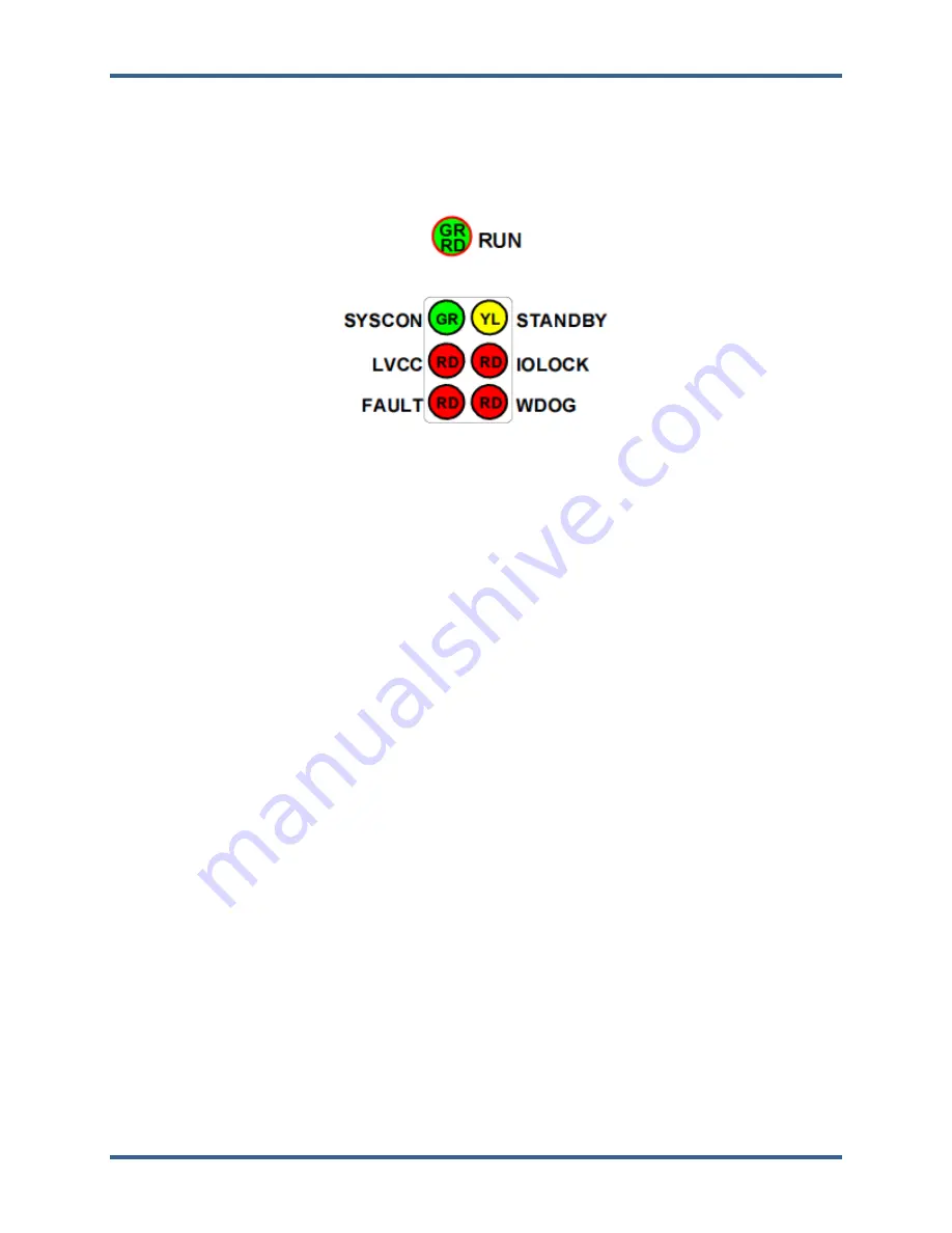
For a CPU that already has the correct application loaded and set to Auto-Start, the following is the
correct/normal sequence of CPU LED indications above through the boot-up initialization routine (times
are approximate):
TIME
1– Fully inserting CPU into kernel rack with KPS on
0:00
LEDs ON—RUN, SYSCON, LVCC, IOLOCK, WDOG
2–
RUN LED
goes OFF
0:05
3–
RUN LED
goes back ON
0:40
4–
FAULT LED
goes ON for 2 sec pulse then back OFF
1:05
5–
LVCC LED
goes OFF
1:20
6–
WDOG LED
goes OFF
1:30
7–
IOLOCK LED
goes OFF, hear relay click, sync complete
1:40
Note:
If you just press the CPU Reset button on the CPU—sequence and time are the same—the
only difference is that the LVCC LED will be OFF the whole time.
Analog and Discrete I/O Modules (Kernel A/B/C: A3-A5)
Each I/O Module has a red Fault LED, controlled by the CPU, that is turned on when the system is reset.
During initialization of an I/O module, which occurs after every CPU reset, the CPU turns the Fault LEDs
on. The CPU then tests each I/O module using diagnostic routines built into software. If the diagnostic
test is not passed, the LED remains on. If the test is successful, the LED goes off. If the Fault LED on a
module is illuminated after the diagnostics and initialization have been run, the module may be faulty or in
the wrong slot.
If during normal control operation all Kernel I/O modules have their Fault LEDs on, check the Kernel CPU
for a failure. If during normal control operation, only one module’s Fault LED is turned on or flashing,
replace this module. A flashing LED indicates that a certain module failure has occurred, and is used by
factory technicians to locate module faults. When a module fault is detected, its outputs are disabled or
de-energized.
Each Analog I/O Module has a fuse in it
. This fuse is visible and can be changed through the bottom of
the plastic cover of the module. If this fuse is blown, replace it with a fuse of the same type and size (24
Vdc/0.1 A).
Released
Summary of Contents for MicroNet TMR 5009FT
Page 65: ...Manual 26518V2 5009FT Installation Hardware Woodward 63 Figure 8 4 DSLC Control Released...
Page 67: ...Manual 26518V2 5009FT Installation Hardware Woodward 65 Figure 8 5 Real Power Sensor Released...
Page 70: ...Manual 26518V2 5009FT Installation Hardware Woodward 68 Released...
Page 71: ...Manual 26518V2 5009FT Installation Hardware Woodward 69 Released...
Page 72: ...Manual 26518V2 5009FT Installation Hardware Woodward 70 Released...
Page 73: ...Manual 26518V2 5009FT Installation Hardware Woodward 71 Released...
Page 74: ...Manual 26518V2 5009FT Installation Hardware Woodward 72 Released...
Page 75: ...Manual 26518V2 5009FT Installation Hardware Woodward 73 Released...
Page 76: ...Manual 26518V2 5009FT Installation Hardware Woodward 74 Released...
Page 77: ...Manual 26518V2 5009FT Installation Hardware Woodward 75 Released...
Page 78: ...Manual 26518V2 5009FT Installation Hardware Woodward 76 Released...
Page 79: ...Manual 26518V2 5009FT Installation Hardware Woodward 77 Released...
Page 80: ...Manual 26518V2 5009FT Installation Hardware Woodward 78 Released...
Page 81: ...Manual 26518V2 5009FT Installation Hardware Woodward 79 Released...
Page 82: ...Manual 26518V2 5009FT Installation Hardware Woodward 80 Released...
Page 83: ...Manual 26518V2 5009FT Installation Hardware Woodward 81 Released...
Page 84: ...Manual 26518V2 5009FT Installation Hardware Woodward 82 Released...
Page 85: ...Manual 26518V2 5009FT Installation Hardware Woodward 83 Released...
Page 86: ...Manual 26518V2 5009FT Installation Hardware Woodward 84 Released...
Page 87: ...Manual 26518V2 5009FT Installation Hardware Woodward 85 Released...
Page 88: ...Manual 26518V2 5009FT Installation Hardware Woodward 86 Released...
Page 90: ...Manual 26518V2 5009FT Installation Hardware Woodward 88 Released...
Page 91: ...Manual 26518V2 5009FT Installation Hardware Woodward 89 Released...
Page 92: ...Manual 26518V2 5009FT Installation Hardware Woodward 90 Released...
Page 94: ...Manual 26518V2 5009FT Installation Hardware Woodward 92 Declarations Released...

