Manual MRI3-ITER GB
Woodward
DOK-TD-MRI3 ITERE Rev.A
43
6.4.5 Checking the operating and resetting values of the relay
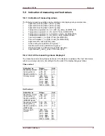
Inject a current which is less than the relay set values in phase 1 of the relay and gradually in-
crease the current until the relay starts, i.e. at the moment when the LED I> and L1 light up or the
alarm out-put relay I> is activated. Read the operating cur-rent indicated by the ammeter. The dev-
iation must not exceed 5% of the set operating value.
Furthermore, gradually decrease the current until the relay resets, i.e. the alarm output relay I> is
disengaged. Check that the resetting current is not smaller than 0.97 times the operating current.
Repeat the test on phase 2, phase 3 and earth cur-rent input circuits in the same manner.
6.4.6 Checking the relay operating time
To check the relay operating time, a timer must be connected to the trip output relay contact. The
timer should be started simultaneously with the current injection in the current input circuit and
stopped by the trip relay contact. Set the current to a value corresponding to twice the operating
value and inject the current instantaneously. The operating time measured by the timer should
have a deviation of less than 3% of the set value or <20 ms.
Repeat the test on the other phases or with the in-verse time characteristics in the similar manner.
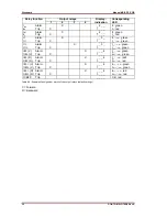
In case of inverse time characteristics the injected current should be selected according to the cha-
racteristic curve, e.g. two times IS. The tripping time may be red from the characteristic curve dia-
gram or calculated with the equations given under "technical data".
Please observe that during the secondary injection test the test current must be very stable. Oth-
erwise the test results may be wrong. This especially applies for currents smaller than 2 x IS ,
where the trip delays are in the steep range of the inverse curves.
6.4.7 Checking the high set element of the relay
Set a current above the set operating value of I>>. Inject the current instantaneously and check
that the alarm output relay I>> operates. Check the tripping time of the high set element according
chapter 6.4.6
Check the accuracy of the operating current setting by gradually increasing the injected current un-
til the I>> element picks up. Read the current value form the ammeter and compare with the de-
sired setting.
Repeat the entire test on other phases and earth current input circuits in the same manner.
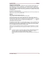
Note !
Where test currents >4 x I
N
are used, the thermal withstand capability of the current paths has to be
considered (see technical data, chapter 7.1
6.4.8 Checking the external blocking and reset functions
By means of the external blocking input, it is possible to block all protective functions. To give an
example, the blocking function of the phase current high set element is described.
This can be tested by first setting the parameter for the phase current high set element to „BLOC“
and then connecting the auxiliary voltage to terminals E8/D8.
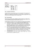
The phase current low set element I> should be set to EXIT for this test. Inject a test current which
could cause a high set (I>>) tripping. Observe that there is no trip of any assigned output relay of
the high set or low set element.
Remove the auxiliary supply voltage from the blocking input. Inject a test current to trip the relay
(message „TRIP“ on the display). Interrupt the test current and apply auxiliary supply voltage to the
external reset input of the relay (terminals C8/D8). The display and LED indications should be reset
immediately.


