Woodward
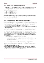
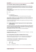
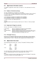
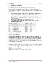
Manual MRN3 GB
38
TD_MRN3_09.08_GB_Rev.New
6.5 Example of test circuit
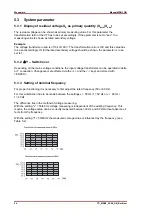
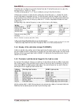
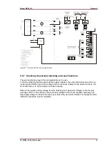
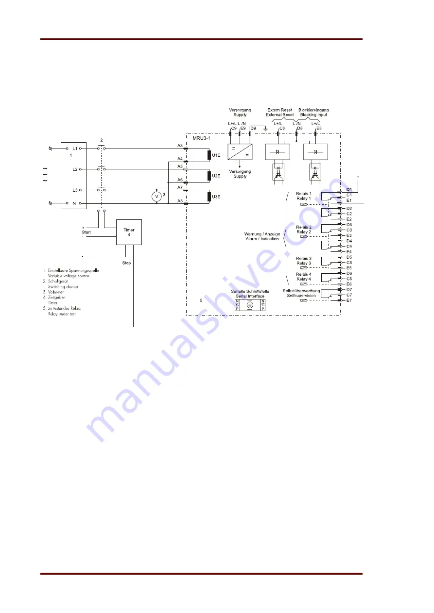
For testing of the MRN3 relay, a three phase volt-age source with adjustable voltage and frequency
is required. Figure 6.1 shows an example of a three-phase test circuit energizing the MRN3 relay
during test. The three phase voltages are applied to the relay in Y-connection.
Figure 6.1: Test circuit
For testing the vector surge function of the relay, a test circuit which can produce phase angle
change (vector surge) is required to simulate mains failures (please refer to chapter 6.5.6).
For testing the df/dt function of the relay, a special test equipment is required, which produces a
constant rate of change of frequency.

