Manual MRN3 GB
Woodward
TD_MRN3_09.08_GB_Rev.New
39
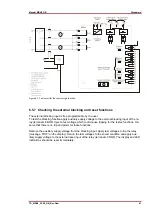
6.5.1 Checking the input circuits and measuring functions
Apply three voltages of rated value to the voltage input circuits (terminals A3 - A8) of the relay.
Check the measured voltages, frequency and vector surge on the display by pressing the push but-
ton <SELECT/RESET> repeatedly. The displayed measuring voltages (shown in Volt) are depen-
dent on the wiring of the input voltage converters and the set transformation ratio.
The voltages are indicated on the display in volts.
At Y-connection:
•
Phase-to-neutral voltages: LED L1, L2, L At Delta-connection:
•
Phase-to-phase voltages: LED L1+L2, L2+L3, L3+L1
The frequency is indicated on the display in Hz: LED f (system frequency = 50.01Hz, Indication =
5001)
The vector surge is indicated on the display in degrees (for MRN3-1): LED
ΔΘ
(Indication
ΔΘ
in °)
The rate of change of frequency (LED df) is indicated on the display in Hz/s (for MRN3-2)
Change the voltages around the rated value and check the measured voltages on the display.
Change the system frequency around the rated frequency and check the measured frequency on
the display.
Compare the voltage and frequency on display with the signal on voltmeter and frequency meter.
The deviation for the voltage must not exceed 1% and for frequency <0.01 Hz.
By using an RMS-metering instrument, a greater deviation may be observed if the test voltage
contains harmonics. Because the MRN3 relay measures only the fundamental component of the
input signals, the harmonics will be rejected by the internal DFFT-digital filter. Whereas the RMS-
metering instrument measures the RMS-value of the input signals.
6.5.2 Checking the operating and resetting values of the over/under
voltage
functions
Note:
When the measuring voltage is connected or disconnected, vector surge tripping or df/dt tripping
can occur. In order to ensure a trouble-free test procedure, the vector surge function or df/dt func-
tion of the relay have to be blocked before tests are started.
Apply three voltages with the rated value and gradually increase (decrease) the voltages until the
relay starts, i.e. at the moment when the LED U> (or U<) lights up or the voltage alarm output relay
(contact terminals D4/E4) is activated. Read the operating voltage indicated by the voltmeter. The
deviation must not exceed 1% of the set operating value.
Furthermore, gradually decrease (increase) the voltages until the relay resets, i.e. the voltage
alarm output relay is disengaged. Check that the dropout to pickup ratio for voltage is greater than
0.97 (for overvoltage function) or smaller than 1.03 (for under voltage).
6.5.3 Checking the relay operating time of the over/undervoltage functions
To check the relay's operating time, a timer must be connected to the trip output relay contact
(Contact terminals D1/E1). The timer should be started simultaneously with the voltage change
from sound condition to a faulty condition and stopped by the trip relay contact. The operating time
measured by timer should have a deviation about 3% of the set value or <20 ms.

