ProAct II Actuator/Driver
Manual 04176
14
Woodward
Power Supply
Power supply output must be low impedance (for example, directly from
batteries).
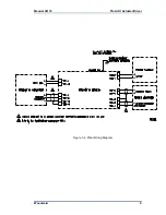
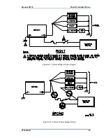
Run an insulated wire directly from the positive (+) battery terminal to the fuse
and the switch as shown in Figure 2-5, then from the switch to the correct
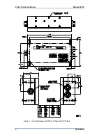
connection on the driver (see Figure 1-4). Run a second insulated wire directly
from the negative (–) terminal of the battery to the driver. Neither of these
connections needs to be shielded (see Figure 2-5 for correct installation).
Run the power leads directly from the power source to the control. DO NOT
POWER OTHER DEVICES WITH LEADS COMMON TO THE CONTROL. If the
power source is a battery, be sure the system includes an alternator or other
battery-charging device (see Figure 2-6 for
incorrect
installation).
When the engine is shut down, the driver powers the actuator to the minimum
stop. If the battery charging system is off when the engine is shut down, this will
cause the battery to be drained. In this case, the power to the ProAct must be
turned off with a switch or relay. Any such switch or relay must be interlocking to
prevent starting the engine when power to the actuator is shut off.
Do not use the driver for normal shutdown procedures. All actuator position
commands should come from the control unit, through the driver, to the actuator.
To prevent possible damage to the control, or poor control
performance resulting from ground loop problems, follow these
instructions.
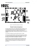
It is important to set up the ProAct driver in the order that follows.
See Figure 2-7 for the location of potentiometers on the driver box.
Always hold onto the side of the control box with one hand while
making an adjustment with the other hand. This prevents possible
static damage to parts.
Use an insulated screwdriver to make adjustments. Extensive
damage is possible should the high voltages present inside the box
be shorted to elements on the board.


