Manual 26710V1
ProTechTPS Total Protection System
Woodward
43
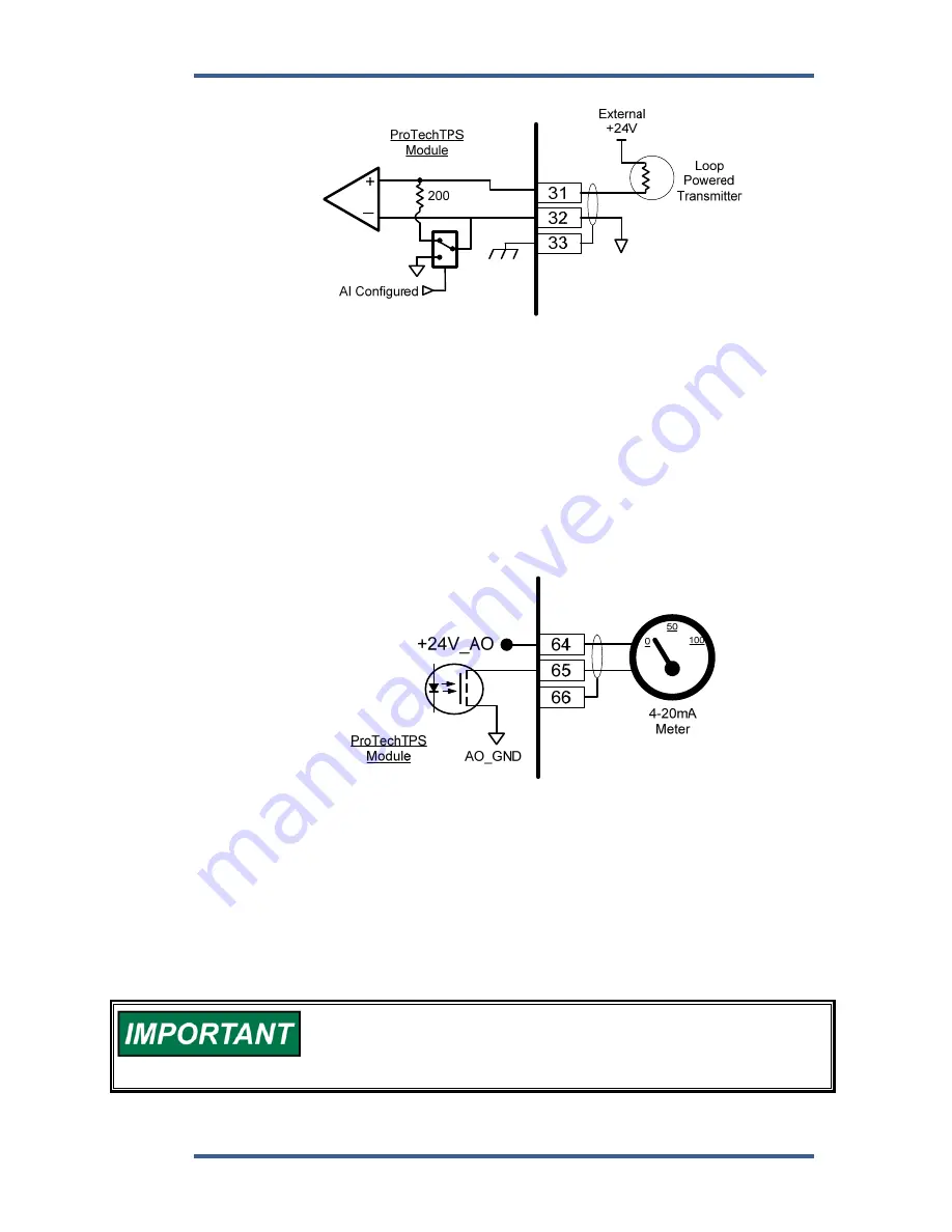
Figure 2-14. Example Configurable Input Wiring—Analog Input
Analog Output
One programmable 4–20 mA analog output per module (A, B, C) is available to
drive a readout meter or interface with other controllers or plant DCS’s
(distributed control systems). This output is designed to drive into an impedance
between 0 to 500
. Twisted shielded pair wiring must be used. Refer to the
Chapter 3 (Functionality) of this manual for applicable analog output
specifications and for information on how to program and use this analog output
in an application.
Figure 2-15. Example Analog Output Wiring
Relay Outputs
Two basic ProTechTPS model variations are available depending on the required
trip system architecture: the “Independent Trip Relay” model and the “Voted Trip
Relay” model. Either version also has 3 programmable Relay Outputs per
module. Refer to Figure 2-16a for the general locations for Trip Relay Output
wiring in the two models.
Optionally all ProTechTPS models can be configured for de-energize-
to-trip or energize-to-trip functionality based on the application
action required. However, de-energize to trip is a safer way to fail so
that a total power loss to the control will trip the prime mover.


