Manual WIP1 GB
Woodward
DOK-TD-WIP1 Rev.F
24
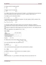
For tripping in case of a single-phase fault:
.
eq.
1
for tripping in case of a 3-phase fault:
eq.
2
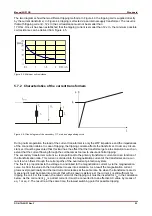
The voltage UL where the flux reaches the value
Ф
s
is called U
max
in the following. Up to this point the trans-
former is still working in its precision class and the cur-rent IL is nearly as high as current I
sec
.
The voltage U
max
can be calculated as follows:
U
max
= I
L
x Z
Lmax
eq.
3
The impedance ZLmax results from the WIP impedance, the cable impedances and the resistance of the
tripping coil during tripping of the WIP1.
Z
Lmax
= Z
WIP
+ Z
Leit
+ R
Sp
eq.
4
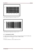
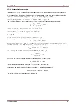
The impedance of WIP1 for the respective pickup value can be found in diagram 1 or diagram 2.
The resistance of the tripping coil can be determined by measuring, or calculated from the rated data of the
coil.
If a transformer is loaded with its rated impedance ZN, the max. power of the C.T. can be determined as fol-
lows:
First of all an explanation for the definition of the C.T. data:
Class: 10P20;
Class 10
P
20
Tolerance 10%
Protection transformer (P)
ü (overcurrent factor)
Capacity: S
N
: 1.5 VA
S
N
: Rated power with rated ohmic resistance and rated current
∙ ü ∙
with ü: overcurrent factor of the current transformer eq. 5
The equation
∙
∙ ü
eq.
6
can be used to calculate the rated impedance of the current transformer as follows:
ü∙
eq. 7
And finally, the rated power of the transformer can be calculated as follows:
∙
eq.
8
Caution:
With a setting value
≥
12 x I
N
the resistance of the tripping coil must not be smaller than 17
Ω
.


