User manual
Hoof trimmingcrush:SA0035
Version: 24-09-14
Page 13 of 29
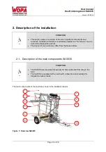
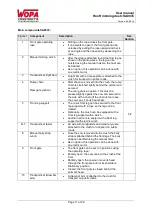
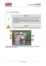
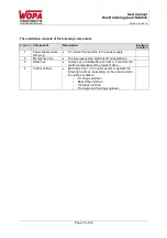
The installation consists of the following components
Figure 2
Component
Description
Section /
location
1
Power supply cable
with plug
To connect the machine to the power supply.
2
Emergency stop
The emergency stop switches off all operations.
3
Relay box
A relay box is installed for each drive. It contains the
control components of the relevant drive.
4
Control buttons
Each drive has 1 or 2 control panels to operate the
following functions, depending on the version and/or
the options available.
o
Front legs up/down
o
Belly strap up/down
o
Hind legs up/down
o
Front legs and hind legs up/down


