11.7 Install the Boiler
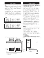
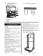
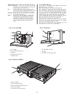
Pull off the clip on facia cover and remove the cabinet by
unscrewing the two fixing screws, releasing the sides and lifting
from the top location.
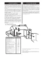
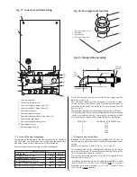
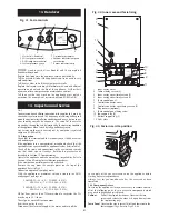
Check that the gas and water valves are closed. Refer to Fig 17.
Fit the new seals, in the hardware pack, to the service valves on
the manifold.
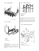
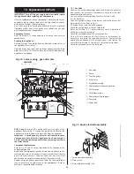
Lift the appliance to the wall, engage in the top support and
lower onto the manifold assembly. Tighten the gas and water
connections.
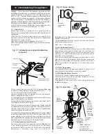
Fit a discharge pipe to the relief valve leading it away from any
electrics or where it might be a hazard. Lower the facia to gain
access. The pipe must not be less than 15mm in diameter and
must run continuously downward outside the appliance. Refer to
Fig 20.
13
65
65
65
65
Wall
Frame
Wall
Frame
CH
Flow
DHW
Flow
Gas
DHW
Cold
Inlet
CH
Return
Fibre
Washer
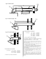
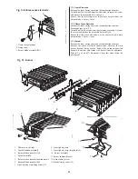
Fig. 17 . Manifold assembly
All dimensions in mm
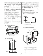
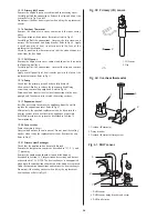
Fig. 20 . Relief valve drain connection
1
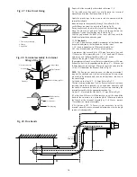
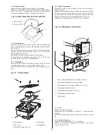
Fig. 18 . Facia cover
1
1. Appliance
2. Controls
3. Facia cover
4. Facia cover clips (4)
2
3
4
Fig. 19 . Wall mounting frame
1. Wall mounting frame
2. Hanging bracket
3. Appliance
4. Support hook
2
1
3
4
5
2
3
4
1. Pump
2. Boiler drain
3. Pressure gauge capillary
4. Relief valve
5. Relief valve drain connection (push fit)


