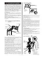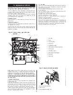
15.2 Spark Electrode
Remove the inner casing cover and the combustion chamber.
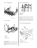
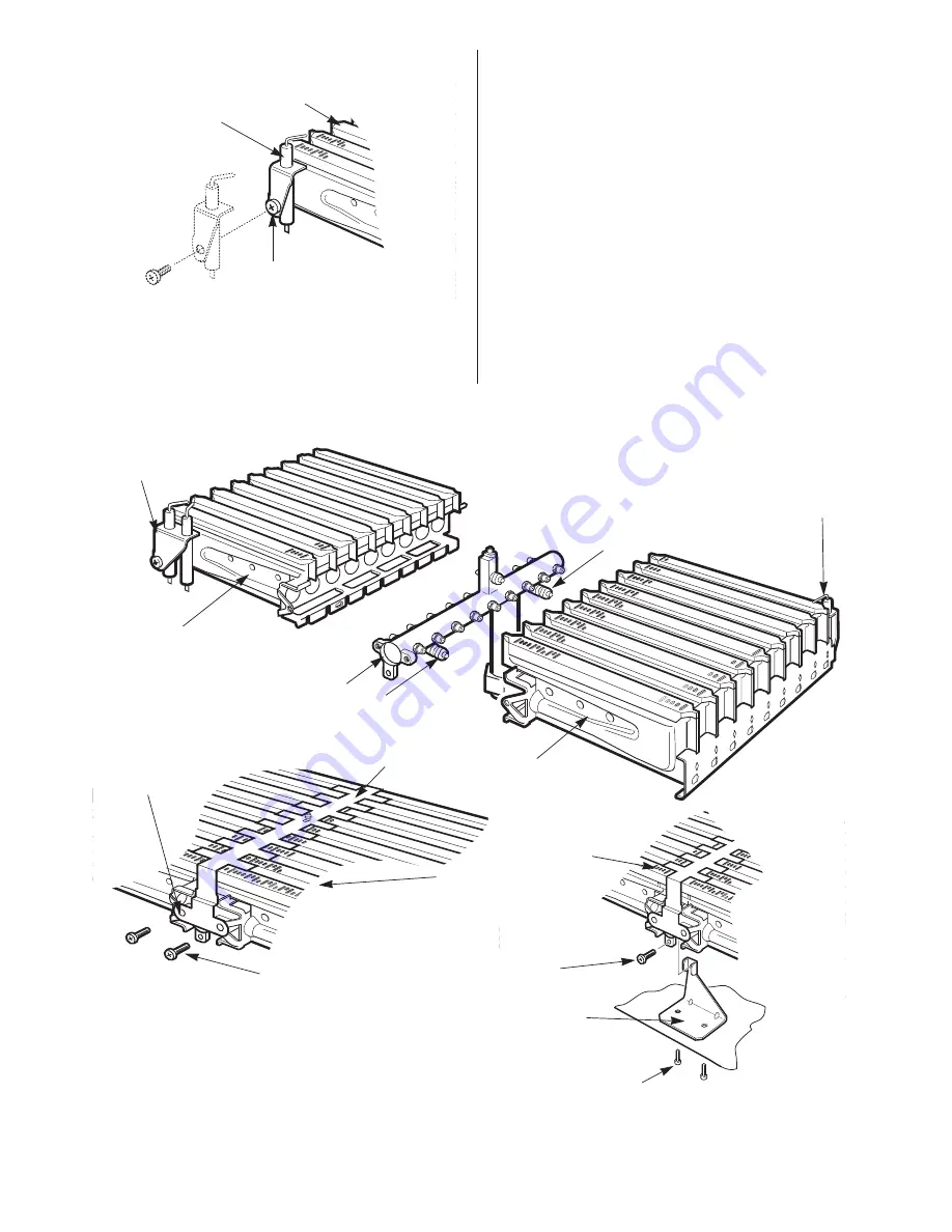
Carefully pull off the lead from the electrode. Unscrew the screw
and remove the assembly. Refer to Fig 49.
Ensure that the electrode is at the correct height above the
burner blade. 6.5mm ±1mm.
15.3 Flame Sense Electrode
Remove the inner casing cover and the combustion chamber.
Remove burner as in 15.4.
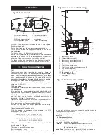
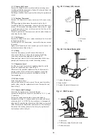
Carefully pull off the leads from the electrode assembly. Unscrew
the screw and remove the assembly. Refer to Fig 50.
Ensure that the sense electrode is at the correct height above
burner blade. 6.5mm ±1mm.
15.4 Burner
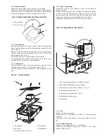
Remove the inner casing cover and the combustion chamber.
Remove the spark electrode connections. Unscrew the two
burner bracket fixing screws. Release the union connection
beneath the burner and remove the burner from the appliance.
Refer to Fig. 46. and 51. Do not omit the gasket when fitting the
new burner.
25
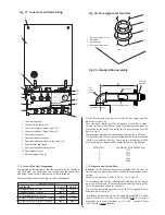
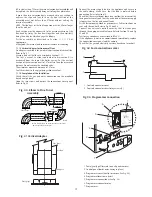
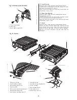
Fig. 50. Flame sense electrode
1
3
2
1. Flame sense electrode
2. Fixing screw
3. Burner blade assembly (RH)
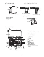
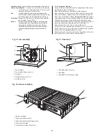
Fig. 51. Burner
1. Flame sense elctrode
2. Spark electrode assembly
3. Burner blade assembly (LH)
4. Burner manifold
5. Burner blade assembly location points
6. Burner blade assembly (RH)
7. Cross- lighting strip fixing screws (2)
6
2
3
1
4
7
5
5
8
9
10
10
13
12
11
8. Cross-lighting strip
9. Cross-lighting strip fixing holes (2)
10. Burner assembly
11. Burner support bracket
12. Burner fixing screw
13. Bracket fixing screws (2)

