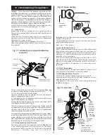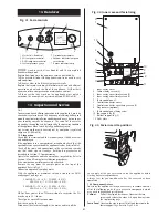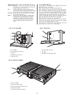
15.9 Inlet Water Filter
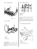
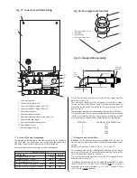
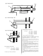
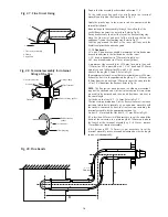
Remove the flow turbine as described in 15.8 preceding.
Taking care, remove flow restrictor assembly from the flow turbine
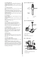
inlet. Refer to Fig 55 Carefully clean wire mesh by back flushing
with water or replace assembly if necessary. Refer to Fig 56.
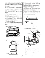
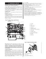
15.10 Control Board
Remove the clip-on facia cover, cabinet and the connections
cover. Carefully disconnect all the electrical connections. Refer to
Fig 35 and 43.
Remove the facia panel and unscrew the four screws and remove
the cover from the rear of the facia. Refer to Fig 57. Lift out the
control board. Refer to Fig 57
Pull out and transfer the transformer to the new board.
Re-commission the appliance to check and set the burner
pressures. Refer to Section 12, Commissioning.
15.11 Transformer
Unscrew the four screws and remove the cover from the rear of
the facia as described in 15.10 preceding. Refer to Fig 57.
Pull out and transfer the transformer to the new board. Refer to
Fig 57.
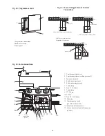
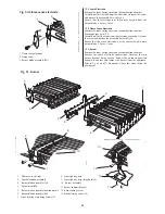
15.12 Clock/Programmer
Remove the facia by gently pulling it away from the boiler to
release the clips.
Remove the clock/programmer assembly by releasing the clip at
the top of the clock/programmer and ease away from the
control panel being careful not to pull on the connector lead.
Unplug the connector at the control board. Refer to Fig 58.
Comprehensive instructions are sent with the new control.
15.13 Fan
Remove the inner casing cover.
Remove the fan as described in Section 14.3, Inspection and
Servicing.
Ensure that all the connections are correctly made to the new
fan.
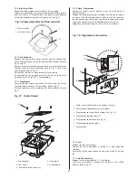
15.14 Air Flow Detector
Remove the fan as described in 15.13 preceding.
Unscrew and withdraw, through the fan outlet, the airflow
detector. Refer to Fig 45.
27
Fig. 57. Control board
Fig. 56.Inlet water filter and flow restrictor
1
2
3
4
5
1. Control panel
4. Transformer
2. Rear cover
5. Control board
3. Rear cover fixing screws (4)
Fig. 58. Programmer connection
1. Facia (gently pull forward to un-clip and remove)
2. Control panel (boiler outer casing in place)
3. Programmer cover (un-clip to remove. See Fig. 34)
4. Programmer location in detail
5. Programmer connections (See Fig. 34)
6. Programmer connector plug
7. Programmer
1
2
3
5
6
4
7
1
2
1. Flow restrictor
2. Inlet water filter

