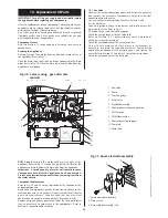
15.15 Primary [ch] Sensor
Remove the clip-on facia cover, cabinet and inner casing cover.
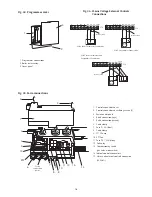
Carefully pull-off the connections. Release the clip and lift out the
sensor. Refer to Fig 59 and 62.
Do not omit the heat transfer paste when fitting the replacement
sensor.
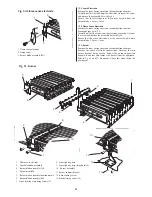
15.16 Overheat Thermostat
Remove the clip-on facia cover, cabinet and the inner casing
cover.
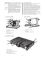
For the position of the overheat thermostat refer to Fig 62.
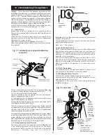
Carefully pull-off the connections. Unscrew the two screws and
remove the thermostat and fixing bracket. Refer to Fig 60. Apply
a small quantity of heat transfer paste to the face of the
replacement thermostat.
Carefully position the thermostat so that the connections are
away from the flue hood.
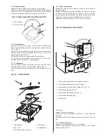
15.17 DHW Sensor
Remove the clip-on facia cover, cabinet and lower the facia onto
the lower support lugs.
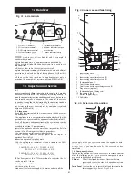
Carefully pull off the connections. Unscrew the clip and remove
the sensor.
Apply a small quantity of heat transfer paste to the face of the
replacement sensor. Refer to Fig 61.
15.18 Pump
Check that the primary circuit has been fully drained.
Use a 4mm Allen key to release the four pump head fixing
screws and remove the pump head. Refer to Fig 48.
Disconnect and transfer the electrical connections to the new
pump head. Take care not to scratch the mating surfaces.
15.19 Expansion Vessel
It will be necessary to remove the appliance from the wall to
replace the expansion vessel. Refer to Fig 37.
Alternatively the specified replacement can be fitted into the
heating system return as close to the appliance as possible.
Re-fill and pressurise the system as described in Section 13
Commissioning.
15.20 Auto Air Vent
Drain the primary circuit.
Unscrew and remove the auto air vent. Do not omit the sealing
washer when fitting the replacement air vent. Remove the cap.
Refer to Fig 37.
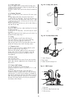
15.21 Primary Heat Exchanger
Check that the appliance has been fully drained.
Remove the temperature sensors as described in 15.15, 16 and
17 preceding.
Remove the combustion chamber, fan and flue hood as
described in Section 14.3, Inspection and Servicing and burner
as described in 15.4. NOTE: The heat exchanger is unsupported
when both the combustion chamber and flue hood are removed.
Undo the four union connections and remove the heat exchanger.
Do not omit the sealing washers when fitting the replacement
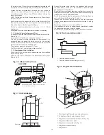
heat exchanger. Refer to Fig 62.
28
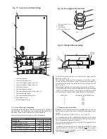
Fig. 59. Primary (CH) sensor.
1. CH Sensor
2. Clip
2
1
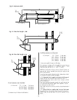
Fig. 60. Overheat thermostat
1
2
3
1. Overheat thermostat
2. Fixing bracket
3. Overheat thermostat fixing screw
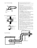
Fig. 61. DHW sensor
1
2
3
1. DHW sensor
2. DHW sensor fixing bracket and screw
3. DHW outlet pipe

