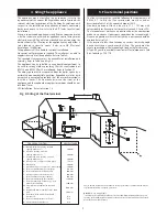
It may be necessary to contact the local Water Company before
connecting the appliance.
Where back-flow prevention devices,
including water meters, are fitted the expansion of hot water into
cold water main can be prevented. This can result in a pressure
build-up that may cause damage to the boiler and household
devices such as showers, washing machines etc.
In these cases we recommend that a mini-expansion vessel be
fitted adjacent to the boiler in the cold water pipe.
The last 600mm of mains water pipe before the appliance must
be in copper.
The domestic hot water circuit of the appliance is suitable for a
mains pressure of upto 10bar. A pressure reducing valve must be
fitted if necessary.
A mains water supply isolating valve is fitted.
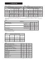
The maximum hot water flow rate is set at the factory to 8 l/min
[24Si II] and 10 l/min [28Si II] giving a nominal temperature rise
of 40
o
C with the temperature control at maximum. This rate is
equivalent to a Specific Rate of 11.5 l/min [24Si II] and 12.9
l/min [28Si II] at a rise of 30
o
C. Refer to Table 6. The temperature
rise, upto the maximum set by the user, is maintained by the
automatic modulation of the heat input.
In winter, when the water temperature is lower it may be
necessary to reduce the water flow at the tap or shower to
maintain the maximum delivery temperature.
It is recommended that long pipe runs to taps or showers are
insulated to prevent the rapid cooling of the water.
Hot and cold taps and mixing valves must be suitable for the
available mains pressure.
No anti-syphonage arrangements are necessary for fixed head
showers. The hose of a loose-head shower must be fixed so that
the shower head cannot get closer than 25mm to the top edge of
the bath to prevent its immersion in the water. Alternatively the
shower can be fitted with an anti-syphonage device at the flexible
hose connection. Thermostatically controlled or pressure
balancing shower valves will give extra comfort and guard
against extreme temperature.
Hot and cold mains water direct to a bidet is, subject to the
approval of the local water company, permissible provided that
the bidet is of the overrim flushing type. The outlets must be
shrouded and unable to be fitted with a hand-held spray. No anti-
syphon arrangements are needed.
LIME SCALE: In areas of temporary hardness [>200ppm of calcium
carbonate] it is suggested that a proprietary scale reducer is fitted
in the mains cold water connection to the appliance. Installation of
a scale inhibitor assembly must be in accordance with the
requirements of the local Water Company. The water hardness can
be determined by reference to the local Water Company.
An isolating valve should be fitted to allow servicing.
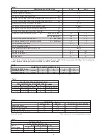
The appliance requires a maximum of 2.8 m
3
/h [24Si II],
3.25m
3
/h [28Si II] of natural gas (G20) or 1.08 m
3
/h [24Si II],
1.25m
3
/h [28Si II] of propane (G31). Refer to Table 7.
A natural gas appliance must be connected to a governed meter.
The installation and connection of the gas supply to the
appliance must be in accordance with BS6891.
The meter (NG) or regulator (LPG) and the pipework to the
appliance must be checked, preferably by the gas supplier, to
ensure that a dynamic pressure of 20mbar for natural gas or
37mbar for propane is available at the appliance (contact gas
supplier if in doubt) equivalent to about 19mbar [NG] or 36mbar
[LPG] respectively at the gas valve inlet pressure connection and
that the gas flow is adequate for all the installed gas appliances
operating together.
Mains supply: 230V ~ 50 Hz 180watts.
External fuse 3A to BS1362. Internal fuses F1-T2A, F2-TI.25A
(20mm). Spare internal fuses are supplied with the appliance.
The mains cable must be 0.75mm
2
(24x0.20 mm) to BS6500 -
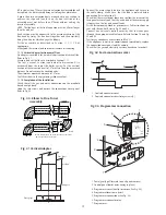
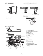
Table 16 and must be connected to the terminal ST2 marked L
(red or brown lead), N (black or blue lead) and the Earth stud
(green or green/yellow lead) and secured with the cable clamp.
The Earth lead must still be slack when the other leads are taut.
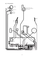
Refer to Fig 14 and 15.
The appliance must be earthed.
The wiring between the appliance and the electrical supply shall
comply with current IEE wiring regulations (and any local regulations
which apply) for fixed wiring to a stationary appliance.
NB
. It must be possible to completely isolate the appliance with at
least 3mm contact separation in both poles.
A room thermostat or externally mounted programmer must be
suitable for mains voltage operation. The leads must be securely fixed
in the cable clamps (see Fig. 35)
A facia mounted digital programmer or mechanical timer or receiver
for wireless programmable room thermostat is available as an
optional extra. Instructions are supplied with the product.
On very rare occasions it may be necessary to fit an external
frost thermostat to protect remote parts of the system. In this
case refer to the WHS Technical Department for information,
Tel: 08705 266241.
10. Electrical
8. Domestic Hot Water
9
9. Gas Supply
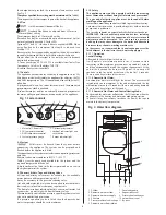
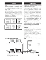
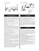
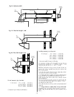
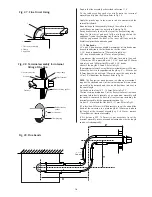
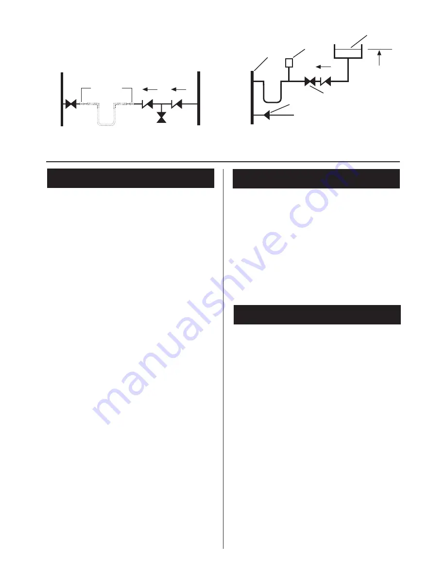
Fig 10 - System Fill
Fig 11 - System make up
1.Central Heating Return
2.Auto Air vent
3.Non-return Valve
4.Make-up Vessel
5.Stop Cock
6.Fill Point
4
1
2
3
5
6
300mm Above
the highest point
of the system
Heating
return
Stop
cock
Hose union
Temporary hose
Non return
valve
Non return
valve
Test cock
Mains water
supply


