AIR PRESSURE SWITCH
2. Air Flow Pressure Switch.
See Fig. 30.
Check that the electricity supply to the appliance is turned off.
Remove the cabinet front panel as described in Section 14.3 (a).
Carefully pull off the sensing tubes and the electrical connections
from the switch.
Unscrew the two screws underneath the gas valve and remove
the switch and bracket from the appliance.
Fit the replacement switch in the reverse order ensuring that the
electrical connections have been made to the correct terminals
on the switch. Check that the sensing tubes are fitted correctly.
3. Fan.
See Fig. 28.
Check that the electricity supply to the appliance is turned off.
Remove the fan assembly as described in Section 14.3(e).
Fit the replacement fan in the reverse order.
Black wire to terminal No. 1. Red wire to terminal No. 3. White
wire to terminal No. 4.
4. Overheat Thermostat.
See Fig. 31.
Check that the electricity supply to the appliance is turned off.
Remove the inner casing cover as described in Section 14.3 (b).
Carefully pull off the two wires from the thermostat head.
Undo the two M3 screws and remove from the appliance.
Fit the replacement thermostat in the reverse order ensuring that
some heat sink compound is between the thermostat and the
plate.
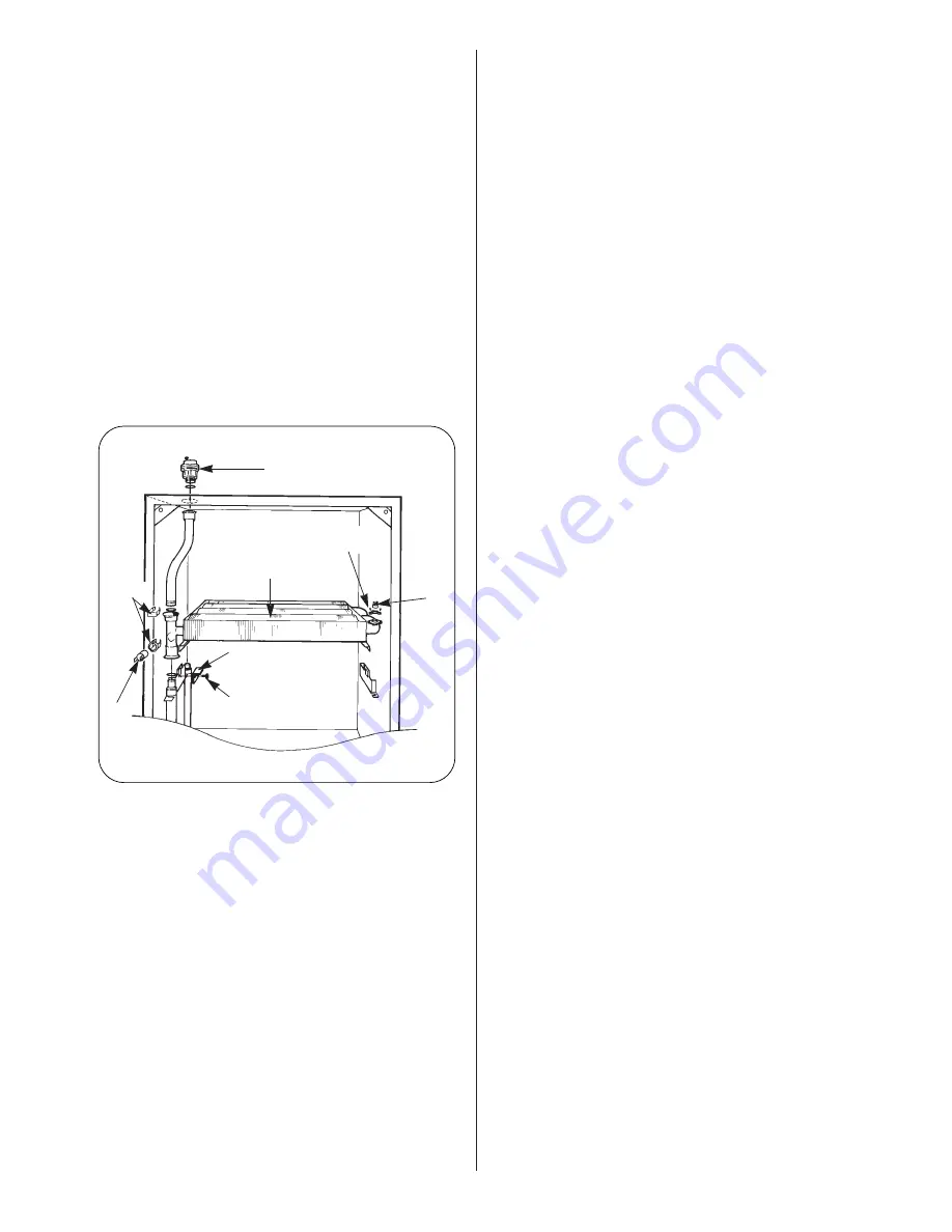
5. Gas to Water Heat Exchanger.
See Fig. 31.
Check that the electricity supply to the appliance is turned off.
Drain the central heating circuit as described in Section 15.3 (a).
Remove the inner casing cover, fan, flue hood assembly, overheat
thermostat, central heating sensor, burner and automatic air
vent assembly as described in Sections 14.3 (b, e, f, g and h),
15.4 (1), 15.4 (4) and 15.4 (13).
Slacken the two screws to remove the two retaining brackets and
lift the heat exchanger from the casing.
Fit the replacement heat exchanger in the reverse order ensuring
that both the “O” rings are correctly fitted and lubricated and a
layer of heat sink compound is on both the thermostats.
Open the valves and fill and re-pressurise the system as
described in Section 12.2.
7. Combustion Chamber Insulation.
Check that the electricity supply to the appliance is turned off.
Drain the central heating circuit as described in Section 15.3(a).
Remove the inner casing cover, fan, flue hood assembly, burner,
and Gas to Water heat exchanger as described in Sections 14.3
(b, e and f), and 15.4 (5). Remove the fibre insulation pads from
the combustion chamber side, rear, and front sections.
Fit the replacement pads in the reverse order taking care not to
damage them.
Open the valves and fill and re-pressurise the system as
described in Section 12.2.
8. Burner.
Check that the electricity and gas supplies to the appliance are
turned off.
Remove the burner assembly as described in Section 14.3 (h).
Fit the replacement burner in the reverse order taking care not to
damage the electrode leads.
9. Burner Injector.
See Fig. 29.
Remove the burner as described in Section 14.3 (h).
Unscrew the brass injector from the burner.
Fit the replacement injector in the reverse order.
10. Spark Electrode Assembly.
See Fig. 29.
Remove the combustion chamber front and sides as described in
14.3 (g)
Carefully pull off the two electrode leads,
Undo the M4 extended nut and remove the spark electrode
assembly from the burner.
Fit the replacement electrode in the reverse order, checking that
the spark gap is 3 to 4mm.
11. Flame Sensor.
See Fig. 29.
Remove the burner as described in sections 14.3(h) and 15.4(8).
Undo the M3 screw and remove the sense electrode from the
burner.
Fit the replacement electrode in the reverse order, checking that
the sense gap is 5 to 6mm.
12. Gas Valve.
See Fig. 25.
Check that the electricity and gas supplies to the appliance are
turned off.
Hinge down the control box assembly in the servicing position
as described in Section 14.3(d).
Undo the two G
3
⁄
4
inch nuts on the gas valve and the two M4
screws on the gas valve bracket and remove the valve from the
appliance.
Whilst supporting the valve carefully pull off the three electrical
solenoid plug connections.
Fit the replacement gas valve in the reverse order ensuring the
sealing washers are correctly fitted.
Turn on the gas supply and check for soundness.
To set the burner pressure.
See Fig. 25.
After a new gas valve has been fitted the burner pressures must
be set.
Follow the procedure described in Section 12.4 – Appliance
Operation.
Turn both the central heating control knob and the domestic
water control knob to their maximum position (i.e. fully
clockwise).
The maximum domestic hot water burner pressure must be set
first as it effects the other pressures.
Turn the gas valve mode switch to the maximum position and
open a hot water tap.
Adjust the maximum pressure adjustment screw on the gas
valve to give a burner pressure of 12.1 mbar for natural gas
(G20).
For propane (G31) the maximum pressure adjustment screw
should be fully screwed in to give a pressure of 35.5 mbar.
Close the hot water tap and turn the gas valve mode switch to
the minimum position.
Adjust the start pressure adjustment screw on the gas valve to
give a burner pressure of 1.0 mbar for natural gas (G20) or 3.8
mbar for propane (G31).
Turn the gas valve mode switch to the normal position.
Ensure the appliance lights in the central heating mode.
Turn the CH pressure adjuster fully clockwise, wait until the
burner pressure has stopped increasing and then slowly turn the
CH pressure adjuster anti-clockwise until the burner pressure is
8.8 mbar for natural gas (G20) or 24.3 mbar for propane (G31).
After completing the adjustments, check the pressure settings
and re-adjust as necessary.
20
Fig. 31. Gas to water heat exchanger.
Auto air vent
Gas to water heat
exchanger
Retaining
clips
Retaining
bracket (2)
Retaining
screws (2)
Overheat
thermostat
Retaining
screws (2)
C.H.
sensor


