Note: 1 bar = 10.2m = 33.5ft of water.
13.3 Set the System Pressure
Fill the system until the pressure gauge is at 2.5 bar and check
for leaks.
Release water from the system using the relief valve test knob
until the required system pressure is obtained, upto a maximum
of 1.5 bar.
Set the pointer on the pressure gauge to record the set system
pressure.
If the pressure indicated on the gauge is greater than 2.65 bar
when operating at the maximum central heating temperature,
an extra expansion vessel must be fitted to the system as close
as possible to the appliance central heating return conection.
The appliance (as despatched) can accomodate a system volume
of 100 litres. Refer to BS7074 Part 1, BS5449 and table 8.
If the system volume is greater then an extra vessel must be
fitted as close as possible to the appliance central heating return
connection and pressurised to the same figure as the integral
vessel.
13.4 Clock/Programmer
The controls fitted to the appliance should be set up at this
stage.
13.5 Operation
Check that the gas and electricity supplies are turned off.
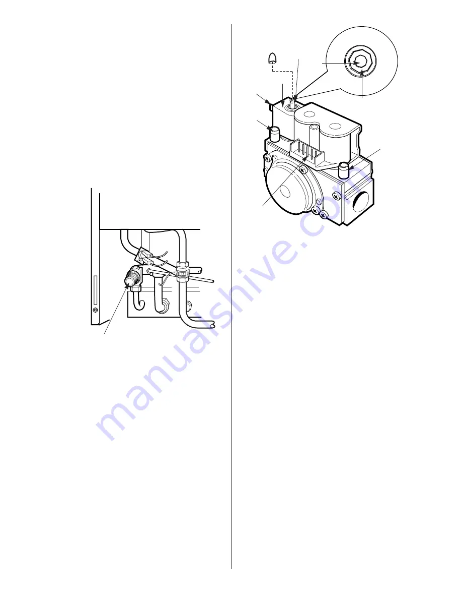
Connect a pressure gauge to the gas valve inlet and outlet
pressure test points. Refer to Fig. 33.
Set the temperature control to maximum and the clock/programmer
to operate continuously.
Turn on the gas and electricity supplies.
Turn on a hot tap to give a maximum flow rate.
A continuous spark will occur until the burner is alight and
sensed by the control circuit.
The burner will remain at its maximum domestic hot water
pressure. Refer to Table 1.
It should not be necessary for the gas valve to be adjusted. Refer
to Section 16.4.11.
Note:
The burner pressure is factory set and if, after checking
that the dynamic (working) supply pressure is sufficient i.e 19-
19.5 mb approx, at the gas valve inlet pressure test point, the
correct pressure cannot be obtained then Worcester Heat
Systems Service Department should be contacted.
If the appliance does not light then check that it is not in the
'Lock-out' state by pressing the reset button. Refer to Fig. 34.
Turn off the hot tap.
The burner pressure will drop to the minimum CH setting and
will ramp up to the maximum central heating pressure.
It should not be necessary for the gas valve to be adjusted. Refer
to Section 16.4.11.
Switch the appliance
off
and then
on
to reset the control.
The burner pressure will remain at the minimum CH pressure for
a period. Refer to Table 1.
It should not be necessary for the gas valve to be adjusted. Refer
to Section 16.4.11.
Test for gas soundness at the joint between the burner and the
gas valve with leak detection fluid.
Turn the electricity supply off then back on to reset the
controls.
13.6 Domestic Hot Water
Turn the central heating temperature control knob fully anti-
clockwise.
Open a hot tap near the appliance.
The burner will light and go to the maximum burner pressure
appropriate to the appliance and the gas. Refer to Table 1.
Gradually close the tap and check that the burner pressure falls.
Fully close the tap and check that the burner goes out.
The fan will continue running until the appliance has cooled to a
pre-set temperature.
13.7 Central Heating
Check that all the radiator valves are open.
Check that the system is pressurised and set to the required
pressure as indicated on the gauge.
Check that the clock/programmer is set to operate continuously.
Set the room thermostat and the central heating control to
maximum.
The burner will light and the appliance will modulate its output
from minimum to satisfy the required heating load.
Check that all the radiators are heating up evenly.
Shut down all but one of the radiators and observe the burner
pressure fall.
Open all the radiators and check that the burner pressure rises.
19
Fig. 32. Pressure relief valve.
Pressure relief valve.
(Turn knob anti-clockwise to test).
Fig. 33. Gas valve.
1
2
3
4
5
6
1 Burner pressure test point
2 Electrical connections – modulator (Blue : Blue)
3 Modulating solenoid
4 Minimum / Maximum pressure adjuster - Allen key
Note:
Clockwise to increase and anti-clockwise to decrease
the pressure
5 Inlet pressure test point
6 Main gas valve connections
Max
2mm
Allen key
Min
3mm
Allen key
Gas valve
sealing
cap


