Installation
Greenstar 4000 – 6 720 891 162 (2020/09)
40
5.5
Electrical connection
DANGER
Risk of electric shock!
▶ Isolate electrical components from the power supply (230 V AC)
(fuse, circuit breaker) and secure against unintentional re-
connection before carrying out any work.
Information on safe isolation can be found in the Health and Safety
Executive guidance HSG85.
▶ Check for zero potential before proceeding with work, using test
equipment approved to GS38 to confirm that the electricity supply is
disconnected.
Electrical considerations:
▶ All electrical work must be carried out by a competent and authorised
person.
▶ All work must comply with the current IET Wiring Regulations.
▶ The isolator shall be situated next to the appliance for new systems
and, where practicable, replacement appliances.
▶ The mains electrical supply to the appliance must be through a fused
double pole isolator.
▶ The isolator must have contact separation of 3mm minimum between
poles. Any system connected to the appliance must not have a
separate electrical supply.
▶ Any additional components that are connected to the appliance that
require 230 Volts must be connected to the same supply as the
appliance.
▶ The correct type of RCD must be employed where additional
protection is required that is suitable for a low energy DC modulating
pump according to IET wiring regulations.
▶ External fuse 3 Amps.
▶ When stripping the wires, ensure copper strands do not fall into the
control box.
NOTICE
Risk of damage from hot appliance components.
Hot appliance components can damage electrical cables.
▶ Ensure all electrical cables are in the correct cable guides and away
from hot appliance components.
Cable routing:
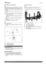
▶ Route cables over the valve bracket avoiding any hot components.
▶ Run power cables separately from signal cables. Interference from
power cables can induce spurious faults on signal cables, ensure that
there is at least 100mm separation between power and signal cables.
▶ Ensure the cables are of sufficient length to allow the control box to
be moved to the service position.
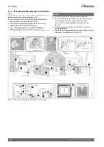
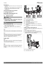
If the power cable is of insufficient length and is to be replaced, access
the connection terminal (
Fig. 57)
▶ Replace with the following cable type:
– H05V2V2F x 0.75 mm
2
(heat resistant PVC, for fixed installation
appliances, in accordance with the latest edition of national and
local wiring regulations)
– A spare strain relief is supplied in the hardware pack, if required.
▶ Connect the cable so that the protective conductor (earth) is longer
than the other wires.
5.5.1
Cable preparations
NOTICE
Damage to control unit!
Small pieces of wire can cause shorts and damage to electronics.
▶ When stripping wires always ensure copper strands do not fall into
the control box.
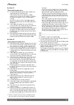
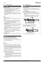
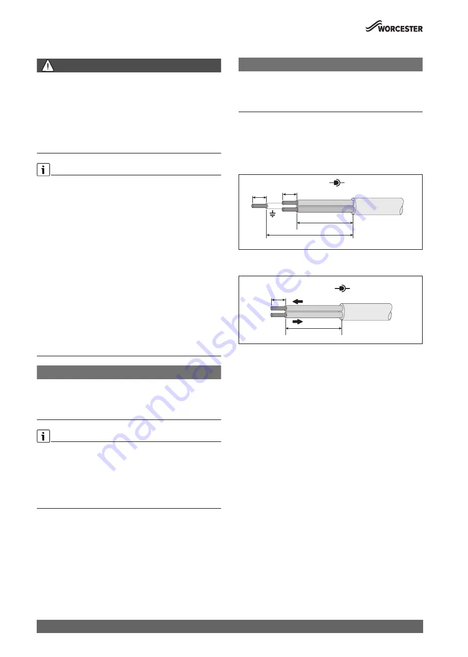
Power supply (power cables)
, example
figure 55
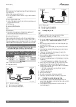
▶ Ensure the conductors (C) can reach the appropriate terminal
connection and that the protective (earth) conductor is longer than
the other wires.
– Power cables connected to the appliance my have different
conductor lengths depending on the termination point.
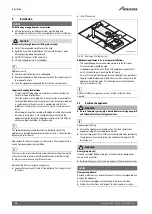
Fig. 55 Power supply (power cables) preparation
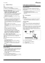
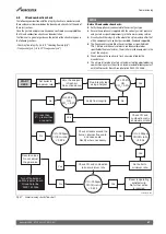
Low voltage (signal cables)
, example
figure 56
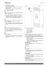
Fig. 56 Low voltage (signal cables) preparation
001002371
1-001
> C
C
6-8mm
6-8mm
N
L
230V
0010012956-001
26-30mm
6-8mm
0-30V

