1.1
General installation information and advice may be obtained
from the Oil Firing Technical Association for the Petroleum
Industry (OFTEC). Training courses are also offered by OFTEC,
leading to inclusion on their list of registered engineers.
1.2
The appliance should be installed by a competent person.
The person installing the appliance should be aware of the
Health and Safety at Work Act and take appropriate action to
ensure that the regulations are adhered to.
1.3
A qualified engineer must commission the appliance before
handing over to the user. OFTEC recommends the use of
registered engineers for the commissioning of oil-fired burners.
1.4
The manufacturers notes must not be taken, in any way, as
overriding statutory obligations.
1.5
The compliance with a British Standard does not, of itself,
confer immunity from legal obligations. In particular the
installation of this appliance must be in accordance with the
relevant requirements of the following British Standards and
regulations in respect of the safe installation of equipment.
BS 5410: part 1: 1997 Code of practice for Oil Fired Boilers.
BS 799: part 5: 1987 Specification for Oil Storage Tanks.
BS 7593: 1992 Code of Practice for treatment of water in
domestic hot water central heating systems.
BS 5449: part 1: 1990 Code of practice for Central Heating for
Domestic Premises.
BS 7074: part 1: 1989 Application, selection and installation of
expansion vessels and ancillary equipment for sealed water
systems.
BS 7671: IEE Wiring Regulations, current edition.
The Building Regulations Part J England and Wales; Part F
Section III Scotland; Part L Northern Ireland.
Local water company bye-laws.
The Control of Pollution (Oil) Regulations.
1.6
To ensure that the installation will perform to the highest
standards, the system and components should conform to those
mentioned in the instructions.
2.1
The Worcester Bosch range of appliances covered in these
instructions have been designed to serve domestic central
heating and hot water requirements ranging from 15 kW to
32 kW ( 51,000 Btu/h to 109,000 Btu/h ) and may be used
on sealed or open vent primary systems.
2.2
The appliances are factory set to burn 28 second Kerosene
heating oil and the output can be altered to suit the application
by adjusting the burner as specified in tables 2 to 4.
2.3
The appliances may be converted to burn 35 second Gas Oil
by changing the nozzle and burner settings as specified in tables
2 to 4.
2.4
A flueless kit is available which allows the user to dispense
with the need for a conventional chimney. The kit incorporates a
silencer which eliminates excessive combustion noise.
Note: It is a mandatory requirement of the building
regulations that only 28 second kerosene is used on low
level discharge flues.
3. Technical Data
2. General Information
1. Installation Regulations
2
1.
Installation Regulations ...........................................Page 2
2.
General Information .................................................Page 2
3.
Technical Data...........................................................Page 2
4.
Siting the Appliance .................................................Page 5
5.
Removal of the Cabinet............................................Page 5
6.
Air Supply..................................................................Page 5
7.
Flue System...............................................................Page 5
8.
Oil Supply ..................................................................Page 7
9.
Heating and Hot Water System...............................Page 8
10. Electrical ....................................................................Page 10
11. Installation ................................................................Page 12
12. Commissioning the Appliance ................................Page 13
13. Instructions to the User ...........................................Page 15
14. Routine Cleaning and Inspection............................Page 16
15. Short Parts List..........................................................Page 17
16. Fault Finding .............................................................Page 18
Contents
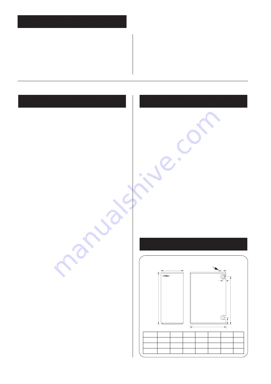
Fig. 1. Principal Dimensions
Model
A
B
C
D
E
F
G
50/70
370
600
855
780
110
92
57
70/90
370
600
855
780
110
92
57
90/110
520
600
855
775
110
92
57
A
C
D
G
F
Flue centre
E
B
Summary of Contents for 70/90
Page 19: ...19 NOTES ...


