background image

Pre-Installation


Worcester Commercial Boiler Series – 6720814332 (2019/04)

18

3.7

Boiler location and clearances

3.7.1

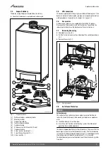
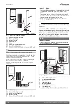
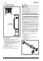
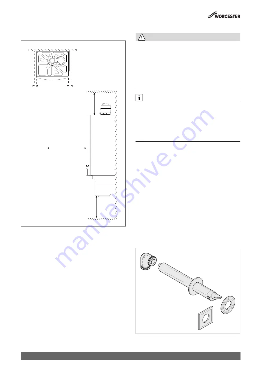
Installation and servicing clearances

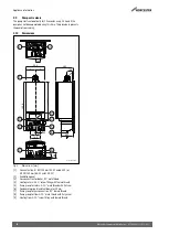
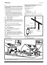
Fig. 21   Clearances [mm]

3.7.2

Compartments

Follow the requirements of BS6798 and BS5440 Part 2 and note:
• Minimum clearances must be maintained.
• If fitting the appliance into an airing cupboard use a non-combustible 

material to separate the appliance from the airing space. The material 
can be perforated up to a maximum hole size of 13mm.

• An access door is required to install, service and maintain the 

appliance and any ancillary equipment.

3.7.3

Bathrooms

If the boiler is fitted in bathrooms, additional RCD (Residual Current 
Device) protection may be required.

Consult the latest version of BS7671 (IEE wiring regulations).

3.8

Flue options

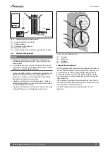
CAUTION: 

in domestic installations

▶ Where a flue system is not going to be accessible, provision must be 

made for service and inspection.

▶ Voids containing concealed flues must have at least one inspection 

hatch no less than 300mm square.

▶ Flue joints within the void must not be more than 1.5metres from the 

edge of the inspection hatch.

▶ Inspection hatches should be located at changes of direction.
▶ If this is not possible, bends should be viewable from both directions.

Groups of appliances with net input in excess of 333kW must comply 
with the Clean Air Act by application to the Local Building control 
department for flue termination approval. Horizontal terminations above 
333kW net input are not permitted (

 IGE/UP/10 latest edition for full 

guidance.)
Horizontal terminations above 70kW net input must comply with the risk 
assessment appendix  9 of IGE/UP/10 as well as the general 
requirements of IGE/UP/10.

3.8.1

Air supply and flue gas exhaust in a room sealed installation

A ventilation cover is integrated into the boilers. This cover houses a 
number of components, such as the burner and the heat exchanger. 
Since this ventilation cover is part of the air supply system, it is vital that 
it is always installed correctly.

To ensure optimal operation, the appliances should be connected to a 
Worcester horizontal or vertical flue terminal. These terminals have been 
developed specifically for Worcester condensing gas boilers and have 
been comprehensively tested for trouble free operation when correctly 
installed. These boilers are also compatible with third party flues if 
required.

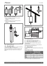
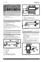
Standard horizontal flue pack (

 fig. 22) for 50-V2 and 65-V2:

• 1: Flue turret 80/125;
• 2: Horizontal flue terminal 80/125;
• 3: Flue finishing kit.

Standard horizontal flue pack (

 fig. 22) for 85-V2 and 100-V2:

• 1: Flue turret 100/150;
• 2: Horizontal flue terminal 100/150;
• 3: Flue finishing kit.

Fig. 22   Standard horizontal flue pack

0010025993-001

300

300

600

25

25

0010025994-001

Summary of Contents for GB162-100 V2

Page 1: ...6720814332 2019 04 GB Installation commissioning and servicing instructions Wall hung gas fired condensing boilers Worcester Commercial Boiler Series GB162 50 65 85 100 V2 ...

Page 2: ...terminal positions 21 4 Transport 22 5 Fitting 22 5 1 Unpacking the boiler 23 5 2 Check gas type 23 5 3 Mounting the boiler 23 5 4 Remove the protective caps 23 5 5 Hydraulic and gas connections 23 5 6 Mounting the pump group accessory 23 5 6 1 Installing the gas isolation valve 24 5 6 2 Mounting the pump group 24 5 7 Hydraulic and gas connections without pump group 24 5 7 1 Gas connection 25 5 7 ...

Page 3: ...12 Check the operating characteristics of the boiler 38 8 13 Final steps 38 8 14 Inform the user 38 8 15 Commissioning report for installations below 70 kW 38 9 Shutdown 39 9 1 Standard shutdown 39 9 2 Shutting down when there is a risk of frost 39 10 Environmental protection disposal 39 11 Inspection and servicing 39 11 1 Important information 39 11 2 Remove the gas air unit 39 11 3 To clean the ...

Page 4: ...eanexplosion Ifyousmellgas observe the following rules Prevent flames or sparks Do not smoke use a lighter or strike matches Do not operate any electrical switches or unplug any equipment Do not use the telephone or ring doorbells Turn off the gas at the meter or regulator Open windows and doors Warn your neighbours and leave the building Prevent anyone from entering the building Wellawayfromthebu...

Page 5: ...stemanddraw the user s attention to any safety relevant action Explain that conversions and repairs must only be carried out by a competent person Pointouttheneedforinspectionsandmaintenance for safe and environmentally compatible operation Leave the installation instructions and the operating instructions with the user for safekeeping Combustible and corrosive materials Do not store or use any co...

Page 6: ...ant Irish standards should be followed including ECTI National rules for electrical installations IS 813 Domestic Gas Installations LPG Installations An appliance using LPG must not be installed in a room or internal space below ground level unless one side of the building is open to the ground Timber framed buildings Where the appliance is to be fitted to a timber framed building the guidelines l...

Page 7: ...cturer for further details You will find the relevant contact details on the back cover of these instructions 2 7 Removing the casing Undo locking screws 1 Pull the 2 click fasteners on the underside of the control panel down 2 Remove the casing 3 Fig 2 Casing removal 2 8 Anti Freeze Protection NOTICE System damage The central heating system may freeze up during severe frost due to intermittent el...

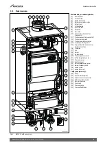
Page 8: ...80 125 mm 50 V2 and 65 V2 or Ø 100 150 mm 85 V2 and 100 V2 2 Ventilation panel 3 Gas connection for boiler R 1 male thread 4 Heating return G 1 screw fitting with female thread 5 Pump group for return G 1 male thread with flat seal 6 Condensate pipe Ø external diameter 24 mm 7 Pump group for gas connection R 1 female thread 8 Pump group for flow G 1 male thread with flat gasket 9 Heating flow G 1 ...

Page 9: ... 10 Combustion air connection concentric 11 Flue gas connection concentric 12 Flue gas testing point 13 Flue gas temperature sensor 14 Incoming air testing point 15 Cap combustion air connection overpressure flue 16 Flue pipe 17 Fan 18 Burner 19 Ignition device 20 Flow temperature sensor 21 Safety temperature sensor 22 Pressure sensor 23 Heat Exchanger 24 Return temperature sensor 25 Boiler ID mod...

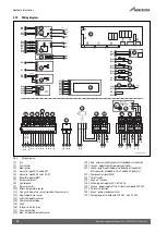
Page 10: ...re dependent controller RTH convertor included in 50 V2 and 65 V2 delivery 22 Pump control signal PWM 23 On off switch 24 Grey no function 25 White power supply 230 V AC 50 Hz 26 Orange power supply of the 1st function module 230 V AC 27 Purple no function 28 Green pump group or external 29 Pump group external pump 230 V AC max 250 W 0010025977 001 D17 D13 D16 C4 C3 C8 C7 A8 A7 A2 A1 A4 A5 G6 G5 F...

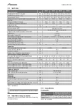
Page 11: ...full load W 6 18 41 6 18 82 6 25 102 6 25 155 Permissible ambient temperature C 0 40 Maximum flow temperature Tmax C 90 Maximum operating pressure PMS bar 4 Maximum condensate accumulation rate l h 6 0 7 6 9 3 11 0 Connections Flue gas connection concentric air supply mm 80 125 100 150 Heating flow return pipe boiler inch G1 Gas connection boiler inch R1 Condensate drain flexible hose external dia...

Page 12: ...171 1 Can be reduced by 3 mbar if measured at the inlet of the gas valve 20 25 GB IE Propane G31 conversion required 251 37 45 Country Gas design pressure mbar Gas category Gas family Default setting mbar GB IE 20 2H 2H G20 20 Appliance type Unit 50 V2 65 V2 85 V2 100 V2 Required flow rate at T 20 K l h 2200 3000 3600 4300 Max flow rate at T 20 K l h 5000 Resistance of boiler with required flow ra...

Page 13: ...should be calculated to ensure no more than the permitted pressure drop between the meter governor to the appliance inlet Commissioning section The meter or regulator and pipe work to the meter must be checked preferably by the gas supplier This is to ensure that the equipment is in good working order and can meet the gas flow and pressure requirements in addition to the demand from any other appl...

Page 14: ...on vessel CH return 2 Pressure relief discharge 3 Drain cock 4 Radiators 5 Zone valves 3 5 Condensate pipe work NOTICE Where a new or replacement boiler is being installed access to an internal gravity discharge point should be one of the factors considered in determining boiler location The condensate pipe must be nominally 22mm Ø plastic pipe Thecondensatepipeworkmustfallatleast52mmpermetretowar...

Page 15: ...ge from boiler 4 Visible air break at plug hole 5 Sink or basin with integrated overflow 6 75mm sink waste trap Condensate trap of 75mm already incorporated into the boiler 3 5 2 External connections NOTICE Freezing conditions Pipe work length should be kept to a minimum and the route as vertical as possible Weather proof insulation must be used NOTICE Condensate waste Care should be taken when si...

Page 16: ... this page run above ground The soak away must use a 100mm Ø plastic tube with two rows of three 12mm holes on 25mm centres and 50mm from the bottom of the tube The holes must face away from the house The tube must be surrounded by at least 100mm of limestone chippings to a depth of 400mm Minimum hole size for the condensate soak away must be 400mm deep by 300mm Ø In situations where there are lik...

Page 17: ...ak away In domestic installations pressure relief drain pipe 1 should be finished with a partial bend near the outlet to face the external wall as shown to help prevent freezing In commercial installations an internal drain in the plant room can be used for both the pressure relief and condensate discharge Fig 20 Pressure relief pipe work 1 Drain pipe 2 Outside wall 3 Drain pipe 4 External drain C...

Page 18: ...liances with net input in excess of 333kW must comply with the Clean Air Act by application to the Local Building control departmentforflueterminationapproval Horizontalterminationsabove 333kW net input are not permitted IGE UP 10 latest edition for full guidance Horizontalterminationsabove70kWnetinputmustcomplywiththerisk assessment appendix 9 of IGE UP 10 as well as the general requirements of I...

Page 19: ...ue length see table 10 Fig 25 Vertical flue length Fig 26 Horizontal flue length A Distance from centre of flue to inside rear wall B Distance from centre wall bracket to centre of flue elbow L Distance from centre of flue to outside wall Take the flue pipe clearances into account when installation the linstallation location Maximum wall thickness without extensions is 415mm Maintain a minimum sid...

Page 20: ...rret 4 finishing kit 5 outer wall 3 8 6 Flue pipe preparation and assembly Measure the flue length L Refer to figures 28 and 29 Fig 28 Flue length rear A 152mm B 337 5mm for Ø 80 125mm horizontal flue 339 5mm for Ø 100 150mm horizontal flue L flue length Fig 29 Flue length side The flue must be inclined from the boiler For connection into the elbow a minimum length of pipe must be maintained The f...

Page 21: ...ical accessory 3 9 2 Room sealed operation The boiler can be connected to a concentric flue gas system The boiler is factory fitted with a concentric connection 3 9 3 Flue material When using 3rd party plastic flue material PPS is recommended 3 9 4 Calculating the air intake and flue gas pipe dimensions The total reduced pipe length is calculated from the sum of the reduced length of the horizonta...

Page 22: ...m distance to a surface facing a terminal unless it will cause a nuisance BS 5440 Part 1 recommends that care is taken when siting terminals in relation to surfaces facing a terminal Installations in car ports are not recommended The flue cannot be lower than 1 000mm from the top of a light well due to the build up of combustion products Dimensionsfromaflueterminaltoafannedairinlettobedetermined b...

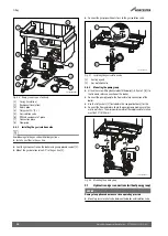
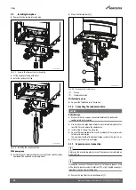
Page 23: ...a spirit level Fig 34 Installing the mounting bracket on the wall Hook the boiler on to the mounting bracket Level the boiler using the set screw 1 and a spirit level Fig 35 Aligning the boiler Mounting on a cascade frame For details on mounting the boiler in a cascade frame see the installation instructions for the cascade system 5 4 Remove the protective caps NOTICE Water damage The boiler may c...

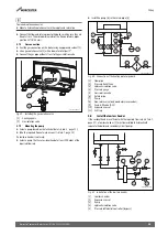
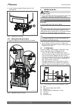
Page 24: ...Fig 37 Installing the gas isolation valve 1 Sealing agents 2 Gas isolation valve 5 6 2 Mounting the pump group Attach the screw fitting delivered with the boiler figure 1 8 to the flow and return connection of the boiler Connect the pump group to the flow and return connection of the boiler Use the flat gaskets 1 included in the scope of delivery for this Connecttheflowandreturnlinetothepumpgroup ...

Page 25: ...ccount tab 7 page 12 If a low loss header is not used Select a pump that has a residual head of at least 200 mbar at the required flow rate Install the pump 6 in the return pipe 5 Fig 40 Connection of the heating water pipework 1 Flow pipe 2 Pressure Relief Valve 3 Hydraulic isolation valve 4 Pressure gauge 5 Gas isolation valve 6 Return pipe 7 Pump 8 Non return valve only mandatory in cascades 9 ...

Page 26: ...e Make sure there is an open connection between the boiler and condensate discharge pipe Use a waste water pipe made of plastic material with a diameter of at least Ø 32 mm to remove the condensate Install a trap in the waste water pipe Connecthorizontalpipesectionswithagradientof53 mmpermetre to the waste water pipe Themaximumlengthofthehorizontalpipesectioninthiscaseis5 m Fill the trap in the wa...

Page 27: ...the electrical connections also observe the documentationandwiringdiagramoftheaccessorybeingconnected chapter 2 12 page 10 6 1 Control principle The boiler is suitable for control according to the principles of room temperature dependent and weather dependent control In the case of room temperature dependent control the user interface in the reference room controls the temperature required within ...

Page 28: ...n the frame Fig 49 Mounting the user interface Turn the locks a quarter turn clockwise then remove the cover Fig 50 Removing the cover Connect the components to the relevant plug Fig 51 Terminal strips 1 24 V AC terminal strip 2 230 V AC terminal strip 6 3 Installation of the strain relief Always pass the cable to be installed through a supplied strain relief mechanism before attaching it to a mai...

Page 29: ...rcial 8000 controls range Formoreinformationonothercontrollersandmodulesthatcanbeused please consult the manufacturer You will find the relevant addresses on the back cover of these instructions Install the modulating controller as specified in the accompanying instructions Connectthemodulatingcontrollerviatheorangeplugontheterminal strip 1 BUS cable Fig 55 Connection of the modulating controller ...

Page 30: ...p Connectthepump spowercabletothegreenconnectorblockonthe terminal strip 2 Fig 59 Connection of pump 6 14 Connecting to the mains DANGER Danger of fatal accident due to electric shock Disconnect the boiler from the mains power supply before working on the boiler Guard against unintentional re connection All Worcester boilers require a permanent live A mains supply of 230 V 50 Hz is required Extern...

Page 31: ... N and up M keys You can navigate the various menus via the arrow keys Press an arrow key to change a setting or value Diagnostic plug An external diagnostic tool can be connected here Burner LED The Burner LED lights up when the burner is firing 7 1 Information menu After a few minutes of inactivity the menu closes automatically and the home screen is displayed Information on the status of the bo...

Page 32: ...omprehensive overview of the display codes and corresponding explanations see chapter 12 Displays an operating code or fault code For a comprehensive overview of the display codes and corresponding explanations see chapter 12 Current operating pressure bar Current boiler flow temperature C Outside temperature C Only displayed with weather compensated control Calculated boiler flow temperature setp...

Page 33: ...ler damage Take the water quality into account when filling the heating system Chapter 3 2 Thetargetchargepressureoftheheatingsystemdepends amongother things on the location of the boiler opening pressure of the safety valve inlet pressure of the expansion vessel Take the above points factors into account when filling the heating system Duringinitialcommissioning theboilerisbroughtintooperationass...

Page 34: ... operation at full load Proceed as follows Take the boiler out of operation Remove the casing Close gas isolation valve Make sure the heating system can dissipate the heat generated Undo the test nipple for the gas supply pressure 1 by turning it through 2 revolutions Fig 65 Open the burner pressure nipple at the 50 V2 and 65 V2 Fig 66 Open the burner pressure nipple at the 85 V2 and 100 V2 Set th...

Page 35: ...e requires no adjustment Only the gas air ratio may be measured If the measurement is out of spec the gas valve must be replaced Take the boiler out of operation Close the gas isolation valve Undo the nozzle pressure test nipple 1 by turning it through 2 revolutions Fig 69 Open the burner pressure nipple at the 50 V2 and 65 V2 Fig 70 Open the burner pressure nipple at the 85 V2 and 100 V2 Connect ...

Page 36: ... into operation 8 9 1 CO and combustion checks The following combustion and flue integrity checks are mandatory from April 2014 and these values must be recorded on the Benchmark check list at the back of this manual Once the gas rate and pressure have been confirmed as acceptable then the CO and combustion checks can be undertaken The boiler case must be fitted whilst these checks are carried out...

Page 37: ...ectify where necessary Turn off boiler and call Worcester Bosch Group help line 0330 123 3366 No Boiler is operating satisfactorily No further action is required No No Verify flue integrity O2 20 6 CO2 0 2 O2 20 6 CO2 0 2 No Yes Check CO and combustion ratio at maximum rate Check CO and combustion ratio at minimum rate CO 350ppm CO CO2 ratio 0 0035 CO 350ppm CO CO2 ratio 0 0035 CO 350ppm CO CO2 ra...

Page 38: ...he DHW temperature and DHW volume 8 13 Final steps Fit the casing Complete the Benchmark checklist 50 V2 and 65 V2 or commissioning report 85 V2 and 100 V2 Place second ID sticker 1 part of the documentation set at the bottom right on the front cover Fig 75 Second ID sticker 8 14 Inform the user Familiarise the user with the heating system and operation of the boiler Explain to the user how the he...

Page 39: ...ecycling or disposal Used electrical and electronic appliances Electrical or electronic devices that are no longer serviceable must be collected separately and sent for environmentallycompatiblerecycling inaccordancewith the European Waste Electrical and Electronic Equipment Directive To dispose of old electrical or electronic devices you should use the return and collection systems put in place i...

Page 40: ...5kW Release the 4 snap fasteners on the burner cover The snap fasteners are under tension Fig 79 Opening the snap fasteners Remove the gas air unit together with the burner cover Fig 80 Remove the gas air unit together with the burner cover 11 3 To clean the burner Remove the burner gasket and replace if necessary Fig 81 Removing the burner gasket 0010010040 001 0010010041 001 2 1 0010010043 001 0...

Page 41: ...ith water if necessary Fig 83 Cleaning the heat exchanger 11 5 Checking the ignition system NOTICE Damage to the glow ignitor The glow ignitor unit is made of breakable material Handle with care NOTICE Damage to the boiler Since the effectiveness of the gaskets in the ignition device is reduced the boiler may be damaged Replace the gasket figure 85 3 and cover plate with gasket figure 85 4 every 4...

Page 42: ...ly into the boiler Remove the condensate trap 2 Fig 87 Removing the condensate trap 1 Threaded connector 2 Condensate trap Flush out condensate trap Fill the siphon completely with water Reattach the siphon Hand tighten the threaded connector 11 7 Cleaning the condensate sump If the siphon is soiled check and clean the condensate sump as necessary Pull the condensate hose down and turn it towards ...

Page 43: ...zzle 1 by turning it through 2 revolutions Fig 91 Opening the burner pressure test nipple 50 V2 and 65 V2 Fig 92 Opening the burner pressure test nipple 85 V2 and 100 V2 Connect pressure gauge Set pressure gauge to 0 Hold the pressure gauge at the same height when the measurement is in progress Open the gas isolation valve Bring the boiler into operation Make sure that the boiler can dissipate the...

Page 44: ...f necessary In doing so take the water quality into account Chapter 3 2 Check the boiler settings Chapter 7 2 Setup menu Replace the front casing and tighten the retaining screws 11 15 Inspection and maintenance reports 0010010060 001 5 Pa 10 Pa 0 Pa 1 2 3 3 2 0010010061 001 1 2 Inspection work Date ___________ Date ___________ Date ___________ Date ___________ Date ___________ Date ___________ 1 ...

Page 45: ...t demand from the on off or modulating control more frequently than 1x every 10 minutes The boiler is on standby The boiler is waiting The actual flow temperature is higher than the calculated or selected boiler temperature Check the boiler temperature on the boiler display Increase the above if necessary Check the heating curve that has been set once the weather dependent control has been adjuste...

Page 46: ... plug of the burner control unit Check the operating characteristics of the boiler by replacing the burner control unit 3 The fan speed is too low 3 The fan does not run during the start phase 3 The fan speed is irregular when starting up 2 Water pressure is too low Topupheatingsystemwithwateruntilapressureof2barisreached Check the expansion vessel Check the heating system for leaks Check the wiri...

Page 47: ...f 105 C Check the water pressure of the boiler vent the heating system and the boiler Check whether it is possible to achieve sufficient flow in the heating system Check the operating characteristics of the pump and the sensor Replace the faulty component if necessary 3 The contacts for the safety temperature sensor haveshortedorthesafetytemperaturesensorhas detected a temperature higher than 130 ...

Page 48: ...nce thermostats if necessary Check the cabling and plug of the gas valve Check the function of the boiler by replacing the gas valve Check the plug and wiring of the burner control unit Checktheoperatingcharacteristicsofboilerbyreplacingtheburner control unit 3 The burner control unit is faulty Check the plug and wiring of the burner control unit Check the operating characteristics of the boiler b...

Page 49: ... with gaskets if necessary 2 A brief power failure has occurred Check whether the fault may have been caused by the presence of a power unit a wind turbine or other equipment that could cause an interruption Check the electrical installation 3 An ionisation current was measured after the burner went out Inspect the ionising part of the ignition device Replace the faulty component if necessary Chec...

Page 50: ...imary water system filter been installed Yes No CENTRAL HEATING MODE measure and record Gas rate m3 hr OR ft3 hr Burner operating pressure if applicable mbar OR Gas inlet pressure mbar Central heating flow temperature C Central heating return temperature C COMBINATION BOILERS ONLY Is the installation in a hard water area above 200ppm Yes No If yes and if required by the manufacturer has a water sc...

Page 51: ...re Signature SERVICE 05 Date SERVICE 06 Date Engineer name Engineer name Company name Company name Telephone No Telephone No Gas safe register No Gas safe register No Record At max rate CO ppm AND CO2 Record At max rate CO ppm AND CO2 Atmin rate Wherepossible CO ppm AND CO2 Atmin rate Wherepossible CO ppm AND CO2 Comments Comments Signature Signature SERVICE 07 Date SERVICE 08 Date Engineer name E...

Page 52: ... Kingdom Tel 0330 123 9559 worcester bosch co uk TECHNICAL SUPPORT 0330 123 3366 RENEWABLE SUPPORT 0330 123 9229 CONTROLS AND CONNECTIVITY TEAM 0330 123 3641 APPOINTMENTS 0330 123 9339 SPARES 0330 123 9779 LITERATURE 0330 123 9119 TRAINING 0330 123 0166 SALES 0330 123 9669 ...

Reviews: