Fitting
Worcester Commercial Boiler Series – 6720814332 (2019/04)
24
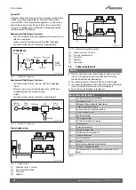
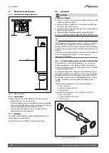
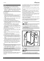
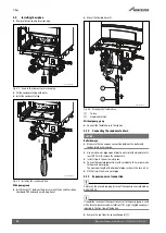
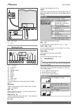
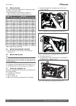
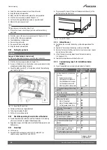
Fig. 36 Pump group scope of delivery
[1]
Casing (insulation)
[2]
Back panel (insulation)
[3]
Return pipe
[4]
Flat gasket 1½" (2 × )
[5]
Gas isolation valve
[6]
PRV and condensate T-piece
[7]
Connection piece
[8]
Flow pipe
5.6.1
Installing the gas isolation valve
Avoid damage to the gas valve with older gas lines.
▶ Install a gas filter in the gas line.
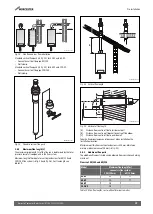
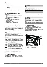
▶ Seal the gas connection on the boiler using an approved sealant [1].
▶ Mount the gas isolation valve G 1" in the gas line [2].
▶ Connect the gas pipe without stress to the gas isolation valve.
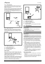
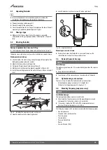
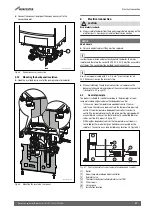
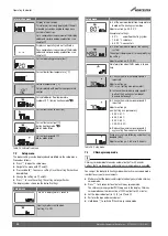
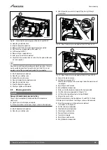
Fig. 37 Installing the gas isolation valve
[1]
Sealing agents
[2]
Gas isolation valve
5.6.2
Mounting the pump group
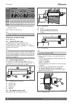
▶ Attach the screw fitting delivered with the boiler (
figure 1, [8]) to
the flow and return connection of the boiler.
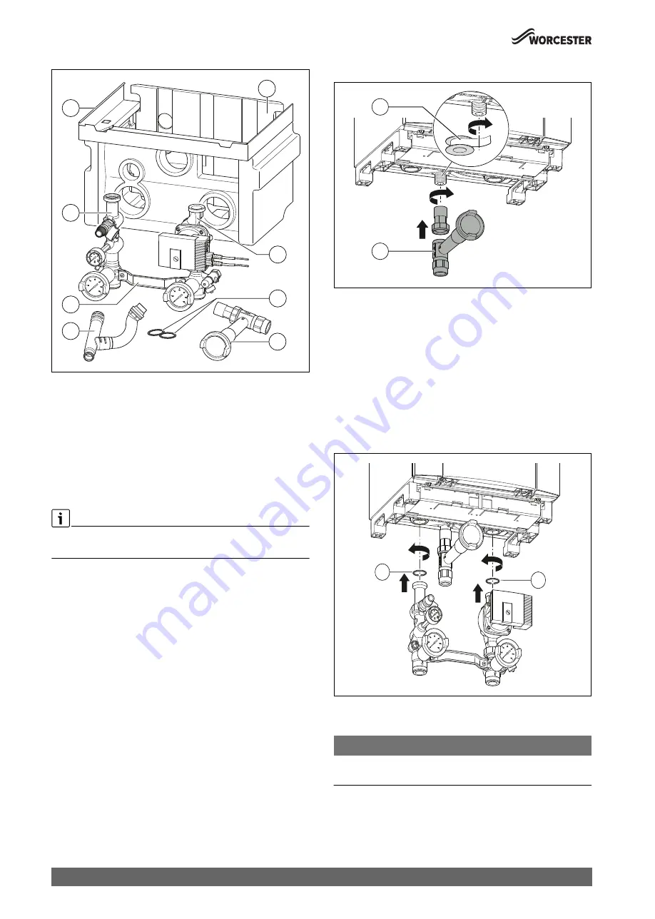
▶ Connect the pump group to the flow and return connection of the
boiler.
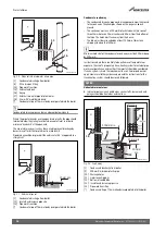
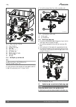
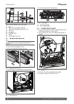
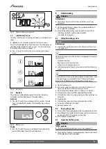
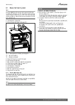
▶ Use the flat gaskets [1] (included in the scope of delivery) for this.
▶ Connect the flow and return line to the pump group, making sure they
are free of stress. The minimum diameter of the supply and return line
must be 1½" (Ø 35 mm).
Fig. 38 Mounting the pump group
5.7
Hydraulic and gas connections (without pump group)
NOTICE:
Damage to appliance due to excessive operating pressure.
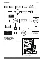
▶ Mount a pressure relief valve between the boiler and isolation valve.
0010009986-001
2
3
4
5
8
1
7
6
0010009988-001
2
1
0010009990-001
1
1

