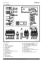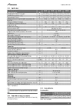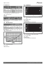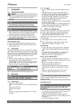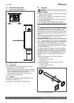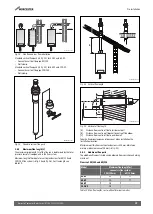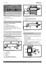
Pre-Installation
Worcester Commercial Boiler Series – 6720814332 (2019/04)
14
System fill:
Filling and refilling of the heating circuit must have been carried out by a
method that has been approved by the Water Regulation Advisory
Scheme (WRAS), for the type of heating appliances, i.e. Domestic (in-
house) Fluid Category 3. Non-Domestic (other than in-house) Fluid
Category 4. Depending on the Fluid Category the approved method
should comprise of the following:
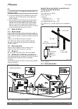
Requirements Fluid Category 3 systems:
• Control valve (stop valve) including a double check valve on the mains
cold water supply pipe.
• Temporary connection to be removed after filling (filling loop).
• Control valve (stop valve) on the heating system pipework.
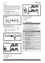
Fig. 9
System fill - category 3
Requirements Fluid Category 4 systems:
• Control valve (stop valve) on the mains cold water supply pipe.
• Strainer.
• Water non-return valve with reduced pressure Zone (RPZ valve
assembly) incorporating a Type BA air gap.
• Tundish.
• Control valve (stop valve) on the heating system pipework.
Fig. 10 System fill - category 4
Typical sealed system
Fig. 11 Sealed system
[1]
Expansion vessel - CH return
[2]
Pressure relief discharge
[3]
Drain cock
[4]
Radiators
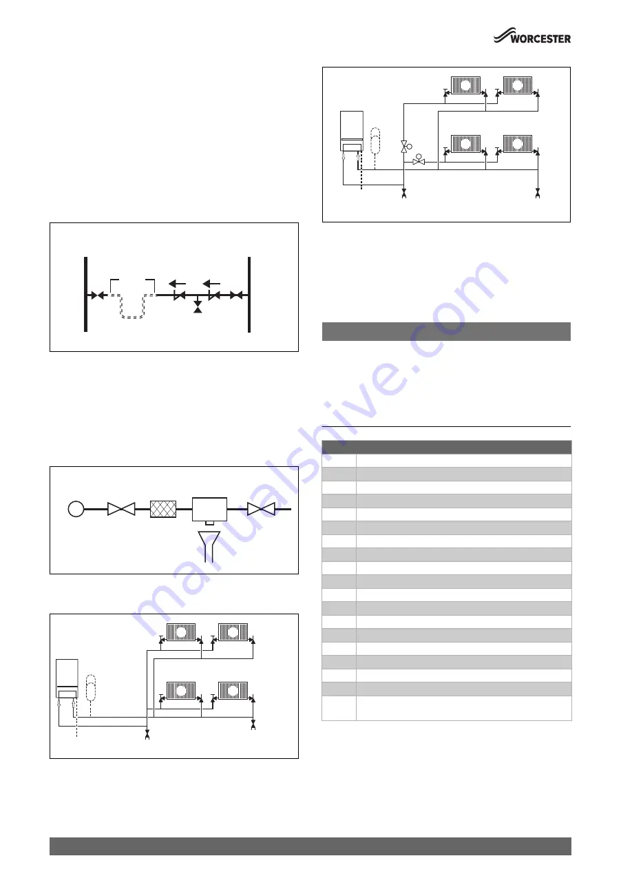
Fig. 12 Sealed system with zone valves
[1]
Expansion vessel - CH return
[2]
Pressure relief discharge
[3]
Drain cock
[4]
Radiators
[5]
Zone valves
3.5
Condensate pipe work
NOTICE:
▶ Where a new or replacement boiler is being installed, access to an
internal “gravity discharge” point should be one of the factors
considered in determining boiler location.
▶ The condensate pipe must be nominally 22mm Ø plastic pipe.
▶ The condensate pipe work must fall at least 52mm per metre towards
the outlet and should take the shortest practicable route.
▶ Ensure there are no blockages in the pipe run.
Table 9
0010025981-001
Heating return
SYSTEM FILL
Hose
return
Stop
cock
Test cock
Non return
valve
Non return
valve
Mains
supply
Temporary hose
Stop cock
0010025982-001
Mains
cold water
Stop
cock
Stop
cock
Strainer
RPZ
Tundish
0010025983-001
3
3
1
2
4
4
4
4
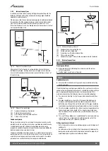
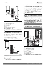
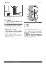
Key to condensate illustrations
1
Condensate discharge from boiler
2
Soil and vent stack
3
Minimum 450mm and up to three storeys
4
Visible air break at plug hole
5
Sink or basin with integrated overflow
6
75mm sink waste trap
7
Condensate pump
8
PVCu strap on fitting
9
100mm Ø minimum plastic pipe
10
Drainage holes
11
Limestone chippings
12
Bottom of sealed tube
13
Insulate and increase pipe size
14
Pipe work transition
15
External air break
16
Air gap
17
External rain water pipe into foul water
18
43mm 90° male/female bend
*
Condensate trap of 75mm already incorporated into the
boiler
0010025984-001
M
M
3
5
3
1
2
4
4
4
4


