Fitting
23
Worcester Commercial Boiler Series – 6720814332 (2019/04)
5.1
Unpacking the boiler
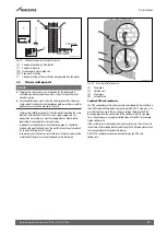
▶ To ensure the connections are not damaged, only remove the
styrofoam at the bottom once the boiler has been hung.
▶ Remove packaging and dispose of it.
▶ Prevent damage to the connections.
▶ Cover the connection for the flue gas/air supply on the top of the wall
mounted gas condensing boiler to prevent ingress.
5.2
Check gas type
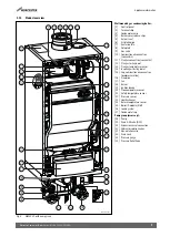
▶ Make sure that the gas type to which the boiler is connected
corresponds to the gas type specified on the data plate (
figure 4,
[8]).
5.3
Mounting the boiler
NOTICE:
Damage to appliance due to incorrect lifting.
▶ Lift the boiler with one hand underneath and the other on top of it.
The boiler may only be hung on the wall or installed on a cascade frame.
Wall-mounted installation
▶ Check whether the wall is strong enough to support the weight of the
boiler, pump group and water content.
▶ Mount a fastening structure if required.
▶ Determine the position of the boiler on the wall.
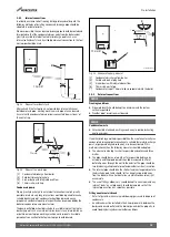
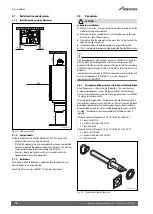
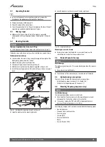
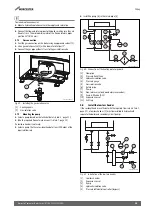
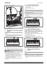
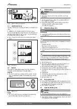
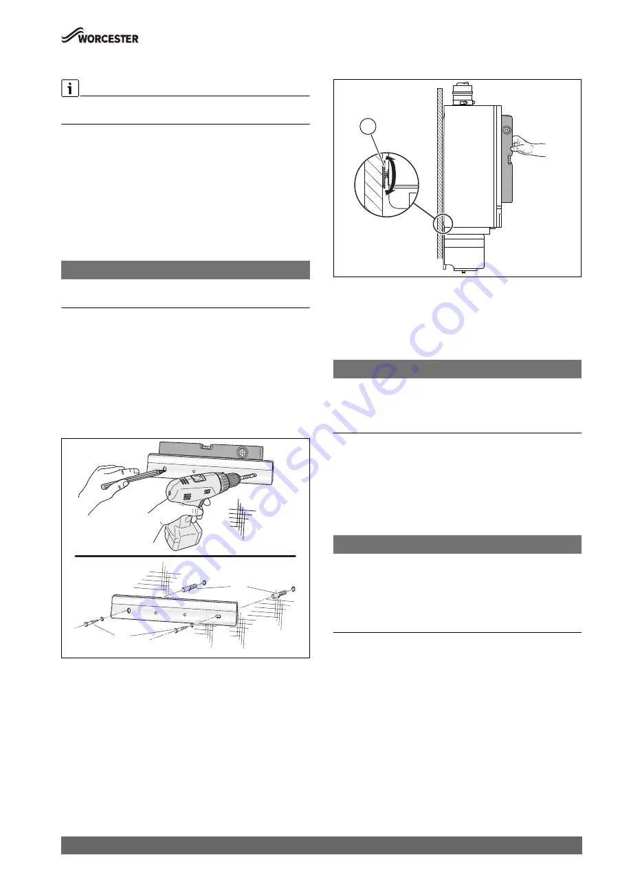
▶ Mark holes using the mounting bracket supplied (
figure 34).
▶ Install the mounting bracket on the wall with the assistance of a spirit
level.
Fig. 34 Installing the mounting bracket on the wall
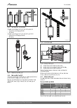
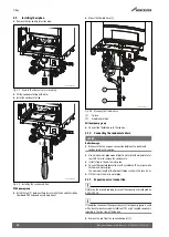
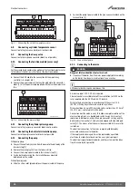
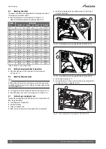
▶ Hook the boiler on to the mounting bracket.
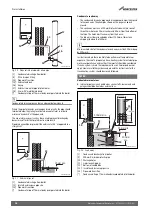
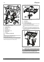
▶ Level the boiler using the set screw [1] and a spirit level.
Fig. 35 Aligning the boiler
Mounting on a cascade frame
▶ For details on mounting the boiler in a cascade frame, see the
installation instructions for the cascade system.
5.4
Remove the protective caps
NOTICE:
Water damage.
The boiler may contain water. This can be discharged when the caps are
removed.
▶ Keep a bucket and cloth handy.
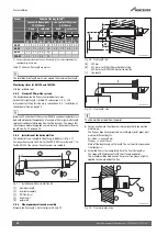
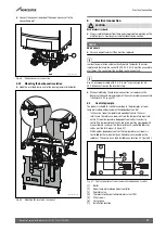
▶ Take the caps off the connections on the underside of the boiler.
5.5
Hydraulic and gas connections
There are 2 ways to make the hydraulic and gas connections:
• Using the pump group (accessory) (
chapter 5.6)
• Without using the pump group (
chapter 5.7).
5.6
Mounting the pump group (accessory)
NOTICE:
Installation damage.
The pump group includes a pressure relief valve.
▶ Check whether the excess pressure, the operating pressure and
components in the heating system suite each other.
▶ If necessary, replace the PRV with a PRV of appropriate excess
pressure. Maximum boiler pressure is 4 bar.
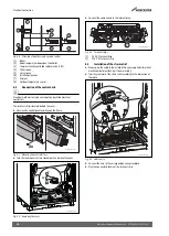
The following components have been incorporated into the pump group:
• Gas isolation valve
• Flow and return isolation valves
• Pressure gauge
• Thermometer
• Pressure Relief Valve
• Pump
• Drain & fill valve (DFV)
0010009982-001
1.
2.
3.
4.
0010009984-001
1

