
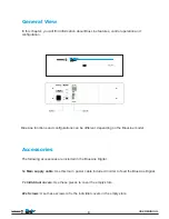

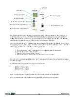
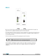
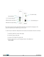
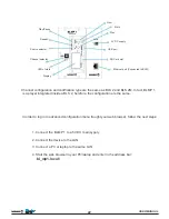
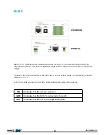
GPI port
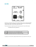
5V power supply
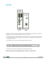
RJ 45 Ethernet port
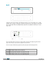
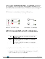
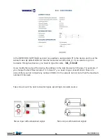
Balanced audio input (IN-B)
Balanced audio input (IN-A)
1 to 16 channel selection
Activity indicator
Alarm connection
GPO port
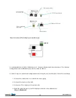
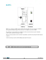
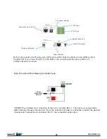
BLS 2M incorporates 4 GPI ports and 4 GPO ports which state is reflected in the GPIO ports of
the BLR devices. If you clese the GPI 2 in the BLS 2M, the unit will send the state al GPO 2 in
all BLR and vice versa. Take into account that when you close one GPI in the BLS 2 M, its state
will appears in all BLR with GPIO, although they are in different channels.
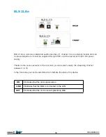
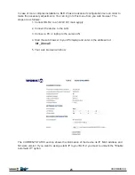
When you act over the GPI 1 in the BLS 2M, all the device in the zone 2 (by default, we considerer
them paging zone or receiver zone) to “listen” in the channel “0" with maximum volume. This will
act the paging function which made the following functions:
1. The unit sends a "push*" message which includes the state of the device.
2. It sends the command "source=0"
3. It sends the command "Mode=Single"
4. It sends the Master, Channel1 and channel 2 volume to 0 dB
When the GPI 1 is disactivated, it sends a "pop*" message which loads the configuration previous
to "push" message.
By default the BlueLine system is configured in two zones:
Zone 1
: For senders
Zone 2
: For receivers
push*: Command usedf to read the state of a device and to store its configuration
pop*: Command used to load the stored configuration through a push command
USER MANUAL
10


