
PowerFLO
™
7800 Series
12 Volt DC Motor-Driven Diaphragm Pumps
Specifications —
Motor:
Type: 12 VDC, permanent magnet, totally enclosed, non-ventilated
Leads: 18 AWG, 12” long
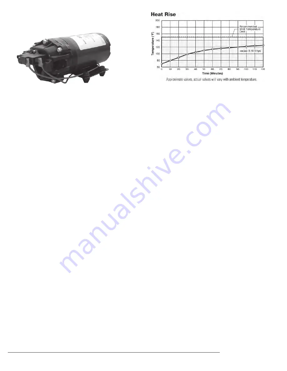
Duty Cycle: See Heat Rise graph
Temperature Limits: Motor is not equipped with thermal
protection. For user safety, optimal performance, and
maximum motor life, the motor surface temperature should
not exceed 150°F (66°C) (see Heat Rise graph above right).
Pump:
Type: 3 chamber positive displacement diaphragm pump, self
priming, capable of being run dry, demand or bypass model.
Certifications: NSF Standard 58
Liquid Temperature: 140°F (60°C) Max.
Priming Capabilities: 14 feet (4 m)
Max Pressure: 60 PSI
Inlet/Outlet Ports: 7802: Quick Attach
Materials of Construction:
Housing: Polypropylene Diaphragm: Santoprene
Valves: Viton
Fasteners: Stainless steel
Weight: 6 lbs (2.7 kg)
Installation and Operation Precautions —
1. The pump is equipped with a pressure sensing demand switch that
controls the maximum operating pressure.
2. In addition, never subject the pump to pressures above 125 PSI
(8.5 bars).
3. As long as there is inlet water pressure, the pump will not stop
forward flow of water even if the motor is turned off. Be sure the
system has positive means of shutting off water supply.
4. Do not operate pump in an explosive environment. Arcing from the
motor brushes, switch or excessive heat from an improperly cycled
motor may cause an explosion.
5. Do not locate the pump motor near low temperature plastics or
combustible material. The surface temperature of the motor may
exceed 250°F (120°C).
6. Do not pump gasoline or other flammable liquids. Pump head
materials are designed for use with water only. Do not use with
petroleum products.
7. Do not assume fluid compatibility. If the fluid is improperly
matched to the pumps’ elastomers, a leak may occur.
8. To prevent electrical shock, disconnect power before initiating any
work. In the case of pump failure, the motor housing and/or pump
fluid may carry high voltage to components normally considered
safe. Therefore, always consider electrical shock hazard when
working with and handling electrical equipment. If uncertain,
consult an electrician. Electrical wiring should only be done by a
qualified electrician per local and state electrical codes.
Pressure Sensing Demand Switch —
The PowerFLO Series 7800 pump is controlled by a built-in pressure
sensing demand switch. When a faucet or valve is opened down stream of
the pump, line pressure drops thus starting the pump automatically.
Conversely, when the valve shuts, the line pressure increases turning the
pump off automatically. The pressure switch actuates in response to the
pump outlet pressure at a predetermined and preset pressure. The pump
label indicates the predetermined ON and OFF pressures. Typically, the OFF
pressure is accurately set at the Factory and the ON pressure is within an
allowable range below that value. In response to the characteristics of the
system in which the pump is installed, the flexibility and length of the
tubing, the faucet or valves and the duration that they are open; these
pressure settings may vary. Therefore, variation in pressure setting is
expected with use and over time.
Adjusting the Pressure Switch:
Should the pressure switch OFF setting vary with use and time to an
unsuitable value, it may be adjusted for optimum performance. Turn the
setscrew clockwise to increase the OFF pressure setting and counter
clockwise to decrease. The screw should not be adjusted more than one
half turn without consulting the Factory. Excessive adjustment of the
pressure switch could cause low system pressure, rapid cycling ON/OFF
operation, and reduced pump and motor life. Damage may occur. The
Warranty does not cover improper adjustment of the pressure switch.
Servicing —
Every Year: Check system against operating standards.
Every 2-3 Years: We recommend replacing the diaphragm and
checking against operating standards.
* Important return safety instructions:
When you return your pump for warranty or repair, you must always do the
following:
1. Flush chemical residue from the pump (best done in the field).
2. Tag pump with type of chemicals having been sprayed.
3. Include complete description of operation problem, such as how pump
was used, symptoms of malfunction, etc. Since pumps can contain
residues of toxic chemicals these steps are necessary to protect all the
people who handle return shipments, and to help pinpoint the reason for
the breakdown.
Model: 7802: 2.0 GPM
PRECISION SPRAY EQUIPMENT
®
, a divison of Green Leaf, Inc. 9490 N BALDWIN ST FONTANET, IN 47851 www.workhorsesprayers.com 800-654-9808
a division of Green Leaf, Inc
®
P R E C I S I O N S P R AY E Q U I P M E N T
PSE
®
®


