— OPERATION
— CALIBRATION
— AFTER SPRAYING
— WINTER STORAGE
— TIP CHART
Tip Spray Pressure Capacity
Tip Spray Pressure Capacity
Tip Spray Pressure Capacity
GALLONS PER ACRE - BASED ON WATER
No. Height
(PSI)
(GPM)
No. Height
(PSI)
(GPM)
No. Height
(PSI)
(GPM)
1 MPH 2 MPH 3 MPH 4 MPH 5 MPH 7.5 MPH 10 MPH
1 MPH 2 MPH 3 MPH 4 MPH 5 MPH 7.5 MPH 10 MPH
1 MPH 2 MPH 3 MPH 4 MPH 5 MPH 7.5 MPH 10 MPH
GALLONS PER 1000 SQ. FT. - BASED ON WATER
GALLONS PER 100 SQ. FT. - BASED ON WATER
3
18"
3
18"
3
18"
10.0
20.0
30.0
40.0
0.30
0.42
0.52
0.60
10.0
20.0
30.0
40.0
0.30
0.42
0.52
0.60
10.0
20.0
30.0
40.0
0.30
0.42
0.52
0.60
1.01
1.40
1.74
2.06
.100
.140
.174
.206
0.50
0.72
0.87
1.00
.050
.072
.087
.100
.340
.480
.596
.688
.034
.048
.059
.068
.254
.360
.440
.500
.025
.036
.044
.050
.204
.290
.350
.408
.020
.029
.035
.040
.135
.190
.236
.270
.013
.019
.0236
.027
44.0
63.0
76.0
90.0
22.0
31.5
38.0
45.0
14.9
20.9
26.0
30.0
11.1
15.7
19.3
22.0
08.9
12.6
15.4
17.8
05.9
08.4
10.3
11.8
.103
.140
.176
.200
.010
.014
.017
.020
4.50
6.30
7.70
8.90
Chemical labels may show application rates in gallons per acre,
gallons per
1000
square feet or gallons per
100
square feet. You
will note that the tip chart shows all three of these rating systems.
Once you know how much you are going to spray then determine
(from
the tip chart) the spraying pressure
(PSI),
and the spraying
speed (MPH).
Conditions of weather and terrain must be considered when
setting the sprayer. Do not spray on windy days. Protective
clothing must be worn in some cases.
Be sure to read the
chemical label carefully.
For the best spray pattern coverage, the nozzles may be rotated
rearward 15°.
To determine the ground speed of your sprayer, measure and mark
driving distances of 100, 200, or 300 feet. Our speed chart indicates
the number of seconds needed to travel these distances. Set your
throttle, and with a rolling start, drive the measured distance of your
choice. Adjust your throttle until you can match the number of driving
seconds needed. Mark the throttle setting and note the gear range
so you can use them while spraying.
Add water and chemicals in the proper amounts in the spray tank and
drive to your starting point. When you are ready to spray, turn your
boom control valve to the “ON” position. Once the pump is turned
on, the unit will begin spraying. The system pressure will decrease
slightly when you see solution flowing from the spray nozzles. This is
normal, the pressure will return as before when you turn the control
valve to the “OFF” position.
You will find optimal spraying in the 20 to 30 PSI range.
After use, fill the sprayer part way with water. Start the sprayer and allow
clear water to be pumped through the plumbing system and out
through the spray nozzles.
Re
fill the tank about half full with plain water and use a chemical
neutralizer such as
Nutra-Sol®
or equivalent and repeat cleaning
instructions. Flush the entire sprayer with the neutralizing agent.
Follow the chemical manufacturer’s disposal instructions of all wash
or rinsing water.
Remove
tips and screens from the boom. Wash tips thoroughly with
water or cleaning solution
(appropria
te for chemical used). Blow out
orifice, clean and dry.
If
orifice remains clogged clean it with a fine
bristle
(not
wire) brush, or with a toothpick. Do not damage the orifice.
Water rinse and dry tips before storing.
Drain all water and chemical out of sprayer, paying special
attention to pump and valves. These items are especially prone
to damage from chemicals and freezing weather.
The sprayer should be winterized before storage by pumping a
solution of
RV
antifreeze through the entire plumbing.
Proper care and maintenance will prolong the life of the sprayer.
— SPEED CHART
Speed in MPH
Time Required in Seconds to Travel a distance of:
(Miles Per Hour)
200 ft.
300 ft.
100 ft.
1.0
2.0
3.0
4.0
5.0
6.0
7.0
8.0
9.0
10.0
68.0
34.0
23.0
17.0
14.0
11.0
9.7
8.5
7.6
6.8
136
68
45
34
27
23
19
17
15
14
205
102
68
51
41
34
29
26
23
20
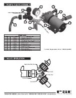
The pumping system draws solution from the tank, through the
strainer and to the pump. The pump forces the solution under
pressure to the boom nozzles and spray wand.
The pump has a pressure switch which will shut the pump off
when it reaches 60 PSI.
Pressure may be regulated by opening or closing the valve
located on the top of the tank. See “Valve Operation” illustrated in
this manual.
The nozzles on the boom will spray an 80 inch wide swath.
Check the nozzle spray pattern by spraying water on a con-
crete surface.
Regularly inspect the suction supply screen on the inside
of the tank. Flush with water to clear any accumulated debris.


