4
6
8
3
5
10
9
To
S
pr
ay
W
an
d
1
11
2
7
Attach Spray
Boom Hose
Assembly Here
1
4
2
3
7
5
6
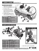
Instruction #1
To Order Replacement Parts: 1-800-654-9808
Deluxe Spot Sprayer Instructions:
3.0 --Install Gauge (item 5) in fitting as
illustrated using a good grade thread
sealant to prevent leaks.
NOTE: DO NOT Overtighten.
3.1 --Insert Lead Wire Assembly (item 14)
into plug at rear of Pump.
3.2 --Join the red wire of the two-wire cable
to a +12V source on the garden tractor,
such as a switch, ammeter, or the positive
battery post. The Black wire (of the two-wire
cable) should be grounded or connected to
the negative battery post.
3.2a --An additional lead is supplied with the Lead
Wire Assembly that will allow the use of a
standard 12V receptacle on the vehicle. This
can be used as an alternate to the battery clips.
DESCRIPTION
STOCK
QTY
ITEM
25 Gallon Tank
600132
1
1
Tank Lid
600133
1
2
Tank Lid Tether
600134
1
3
Spray Wand and Hose Assembly
600147
1
4
Spray Wand Clip
600151
1
5
Wand Clip Screw
600152
1
6
Lead Wire Assembly with Switch (96”)
600153
1
7
Parts List
— GENERAL ASSEMBLY
Parts List
DESCRIPTION
PART NUMBER
QTY
ITEM
Y-
G
arden
H
ose Valve
600122
1
1
Suction
H
ose
6001
55
1
2
G
auge 0-100 PSI
600129
1
3
1
8
.
5
mm Dia. Pinch Clamp
600149
2
4
N3400 P Fitting
6001
54
1
5
Pan
He
ad Screw 10-24 UNC x 1 1/4"
6001
3
0
4
6
Relief
H
ose Assembly
60021
3
1
7
8
EL38QD
P Fitting
600
185
1
2.0 GPM 12V Pump
630183
1
9
Q
D Cross Fitting
600211
1
10
#10 x
3
" Self Tapping Screw
600210
2
11
PRECISION SPRAY EQUIPMENT, a divison of Green Leaf, Inc. 9490 N BALDWIN ST FONTANET, IN 47851 www.workhorsesprayers.com
a division of Green Leaf, Inc
®
P R E C I S I O N S P R AY E Q U I P M E N T
PSE
— PUMP & VALVE ASSEMBLY
Y-VALVE OVERHEAD
To Spray Wand
This lever adjusts
the system pressure
by relieving liquid
back to the tank.
Adjusting this lever
will increase or
decrease pressure
to the spray wand.
Accessory Port
(not used)
Relief Hose
to top of Tank
Pump


