background image

12

SAFETY SIGN LOCATION

The types of safety signs and locations on the equipment are shown in the illustration

below. Good safety requires that you familiarize yourself with various safety signs, the type
of warning and the area, or particular function related to that area, that requires your
SAFETY AWARENESS.

The model and
serial number
plate is located
on the right side
of main frame.

Models

2790A & 27108A

Models 

2150, 2160 & 2172

Summary of Contents for SBC-2160

Page 1: ...3 Preview the assembly instructions in your operator s manual before proceeding further 4 If the assembly instructions call for parts or assemblies to be blocked up use only blocking material that is...

Page 2: ...___________ Serial Number _______________________________ RETAIL CUSTOMER S RESPONSIBILITY It is the Retail Customer and or Operator s responsibility to read the Operator s Manual to operate lubri cat...

Page 3: ...ted to transportation charges other than normal freight charges cost of installation other than cost approved by Worksaver duty taxes charges for normal service or adjustments loss of crops or any oth...

Page 4: ...equipment is used by any person other than yourself is loaned or rented to make certain that the operator prior to operating 1 Reads and understands the operator s manuals 2 Is instructed in safe and...

Page 5: ...o not modify the equipment in any way Unauthorized modification may impair the function and or safety and could affect the life of the equipment In addition to the design and configuration of this imp...

Page 6: ...m ROPS and a seat belt that is used Always stop the tractor skid steer or forklift set brake shut off the engine remove the ignition key and lower loader and attachment to the ground before dismount i...

Page 7: ...engine Always shut off power unit and shift to Park or set brakes when leaving unit Always lower bucket or attachment to ground relieve all hydraulic pressure Remove key when leaving equipment unatten...

Page 8: ...of loader and attachment on power unit while turning OPERATIONAL SAFETY continued Do not lift or carry anyone on loader or in bucket or on attachment ALWAYS lower loader to the ground or block securel...

Page 9: ...void bouncing and momentary loss of steering control Plan your route to avoid heavy traffic Always install transport locks pins or brackets before transporting Do not drink and drive Watch for traffic...

Page 10: ...is blocked securely Never depend on hydraulic system to keep imple ment in raised position Always use personal protection devices such as eye hand and hearing protectors when performing any service o...

Page 11: ...er and first aid kit should be kept readily accessible while performing maintenance on this equipment Following operation or when unhooking stop the tractor set the brakes shut off the engine relieve...

Page 12: ...wash the same area with soap and water 2 Allow the surface to fully dry 3 Remove the backing from the safety sign exposing the adhesive surface 4 Apply the safety sign to the position shown in the dia...

Page 13: ...low Good safety requires that you familiarize yourself with various safety signs the type of warning and the area or particular function related to that area that requires your SAFETY AWARENESS The mo...

Page 14: ...ed for farm tractor front end loaders Optional mounting brackets need to be ordered They are avail able to fit most popular quick coupler front end loaders or pin on type loaders The Models SBG 2790A...

Page 15: ...the 5 8 x 3 I D U bolts Leave the U bolts loose Measure the width of each loader arm at the lower end where the lower pin goes through Then position the mounting brackets on each side for this width p...

Page 16: ...uires 11 4 diameter pins please ask your dealer to order adapter bushings part 830319 Be sure to indicate how many adapter bushings are required ASSEMBLY TRACTOR LOADERS PIN ON ATTACHMENT 2160 2172 MO...

Page 17: ...ur brand and model loader Measure the width of the front adapter on your loader and locate the Quick Attach brackets on the main frame Locate these brackets so the main frame will be centered on your...

Page 18: ...ape to fasten hose on loader arm to keep it in place Make sure the hose routing and length is adequate for your particular make and model loader IMPORTANT Make sure connectors are clean prior to assem...

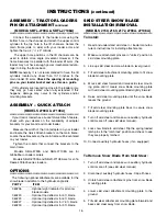
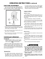
Page 19: ...designed for moving snow and loose dirt Do not abuse blades by prying rocks or stumps with high impact loads Skid shoes should always be used for snow applica tions When moving snow do not operate wi...

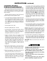
Page 20: ...for installation If some of the locations you will be moving snow have various obstructions you may want to also install the cross over relief valve kit 360065 Upon striking an obstruction the cross...

Page 21: ...up with holes in the top lip of the pivot box A NOTE The above figure is a model 2790A snow blade the tabs for models 2160 and 2172 are located to the outer edge of the pivot box Allow for additional...

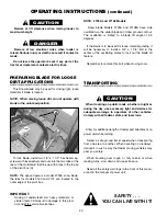
Page 22: ...eed help your dealer has trained service technicians available For your protection read and follow the safety information in this manual MAINTENANCE Inspect the blade for loose damaged or worn parts a...

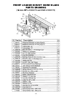
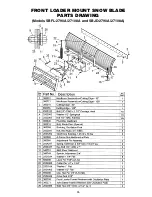
Page 23: ...22 FRONT LOADER MOUNT SNOW BLADE PARTS DRAWING Models SBFL 2160 2172 and SBJD 2160 2172...

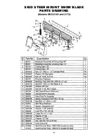
Page 24: ...23 SKID STEER MOUNT SNOW BLADE PARTS DRAWING Models SBS 2160 and 2172...

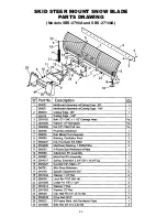
Page 25: ...24 SKID STEER MOUNT SNOW BLADE PARTS DRAWING Models SBS 2790A and SBS 27108A...

Page 26: ...25 FRONT LOADER MOUNT SNOW BLADE PARTS DRAWING Models SBFL 2790A 27108A and SBJD 2790A 27108A...

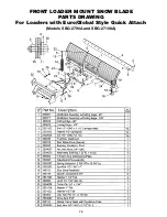
Page 27: ...26 FRONT LOADER MOUNT SNOW BLADE PARTS DRAWING For Loaders with Euro Global Style Quick Attach Models SBG 2790A and SBG 27108A...

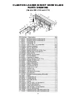
Page 28: ...27 CLAMP ON LOADER MOUNT SNOW BLADE PARTS DRAWING Models SBC 2160 and 2172...

Page 29: ...28 MINI SKID STEER MOUNT SNOW BLADE PARTS DRAWING Model SBMS 50...

Page 30: ...29 MINI SKID STEER MOUNT SNOW BLADE PARTS DRAWING Model SBMS 50 B G...

Page 31: ...30 OPTIONAL HYDRAULIC ANGLE KIT 360170 For Compact Tractor Front Loader Applications For Small Skid Steer Power Units Models SBMS 50 2160 2172 Blades and Clamp On...

Page 32: ...31 OPTIONAL HYDRAULIC ANGLE KIT 360165 For Skid Steer Power Units For Model SBS 2790A only...

Page 33: ...32 OPTIONAL HYDRAULIC ANGLE KIT 360168 For Tractor Front Loader Applications For Model SBFL 2790A only...

Page 34: ...33 HYDRAULIC ANGLE KIT 360165 WITH CROSS OVER RELIEF VALVE KIT 360065 For Skid Steer Power Units Standard on Model SBS 27108A and Optional on Model SBS 2790A...

Page 35: ...34 HYDRAULIC ANGLE KIT 360168 WITH CROSS OVER RELIEF VALVE KIT 360065 For Tractor Front Loader Applications Standard on Model SBFL 27108A and Optional on Model SBFL 2790A...

Page 36: ......

Page 37: ......

Page 38: ...35 OPTIONAL MARKER KIT 360235...

Page 39: ...NOTES...

Page 40: ...rator should be permitted on power unit when in operation no riders allowed Make certain everyone is in the clear before starting power unit or raising or lowering equipment Operate the power unit and...

Reviews: