background image

World Cat

2-3 

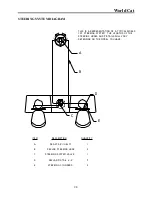
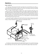
STEERING SYSTEM DIAGRAM

P

O

R

T

S

T

B

D

A

B

C

E

D

ITEM

A

B

C

D

E

DESCRIPTION

STEERING CYLINDERS

KEVLAR PIGTAIL 4’−6’

KEVLAR STEERING HOSE

STEERING SYSTEM VALVE 

SEA STAR II HELM

QUANTITY

2

3

2

1

1

THIS IS A REPRESENTATION OF A TYPICAL WORLD 
CAT STEERING SYSTEM.  THE LENGTHS OF THE 
STEERING HOSES AND PIGTAILS WILL VARY 
DEPENDING ON THE MODEL YOU HAVE.

Summary of Contents for 2006 320EC

Page 1: ...2009 OWNER S MANUAL ...

Page 2: ...ing the warranty card pro vided by the factory The form is in triplicate with one copy for you the dealer and the factory Keep your copy in a secure place so it can be referenced quickly in the event of a warranty issue The 10 year limited hull warranty is transferable and a copy is included at the back of this manual should you decide to sell your boat DEALER RESPONSIBILITIES Our dealers are an e...

Page 3: ...n invitation to join Team World Cat and a survey to rate your pur chasing experience and the initial impressions of our company We ask that you join our family of owners and let us know your feelings about the purchase and the quality of our product MANUAL LEGEND Throughout this manual you will encounter signals to alert of important information Text printed in bold letters and the warning system ...

Page 4: ...Y INFORMATION 1 2 POLLUTION REGULATIONS 1 3 OIL AND HAZARDOUS SUBSTANCES 1 3 DISPOSAL OF PLASTICS DUNNAGE GARBAGE 1 3 BOATING SAFETY GUIDELINES 1 4 PRE DEPARTURE 1 4 LAUNCHING 1 4 UNDERWAY 1 4 RETURNING 1 4 TRAILERING 1 5 ANCHORING 1 5 SHALLOW WATER 1 5 EMERGENCY SITUATIONS 1 6 EMERGENCY STOP SWITCH 1 6 COMMUNICATION 1 6 RENDERING ASSISTANCE 1 6 REPORTING ACCIDENTS 1 6 WEATHER 1 6 TOWING 1 6 CARBO...

Page 5: ...G CHARACTERISTICS 2 5 ADVERSE SEA CONDITIONS 2 5 BOATING TIPS 2 6 PERFORMANCE FACTORS 2 6 ENGINE EFFICIENCY 2 6 PROPELLER CONDITION 2 6 WEATHER CONDITIONS 2 6 LOAD 2 7 MARINE GROWTH 2 7 BOTTOM PAINT 2 7 Chapter 3 Systems Information OVERVIEW 3 1 FUELING GUIDELINES BEFORE FUELING 3 1 DURING FUELING 3 1 AFTER FUELING 3 1 FUEL SYSTEM 3 2 FUEL SYSTEM DIAGRAM 3 2 ELECTRICAL SYSTEM 3 3 BATTERY SYSTEM 3 ...

Page 6: ... 9 SUZUKI 3 9 PLUMBING SYSTEMS 3 9 Chapter 4 Maintenance and Service OVERVIEW 4 1 GELCOAT MAINTENANCE 4 1 CLEANING 4 1 WAXING 4 1 REPAIR 4 2 BOTTOM PAINT 4 2 UPHOLSTERY 4 3 TRIM PLEXIGLASS POLYETHYLENE 4 3 STAINLESS ALUMINUM 4 3 BILGE COMPARTMENTS 4 3 COCKPIT DRAINS 4 3 WINTERIZATION 4 4 Chapter 5 Model Specific TABLE OF CONTENTS 5 1 MODEL SPECIFIC INFORMATION FOR YOUR BOAT Warranty Information ...

Page 7: ...World Cat ...

Page 8: ...quired by federal and state law to be registered in the state where they are primarily used Registra tion numbers and validation stickers must be displayed per regulations and a certificate of registration must be on board while the vessel is being operated When traveling away from your home waters contact authorities at your destination to determine if any additional registration is required Some...

Page 9: ... remaining on the boat should a failure occur Remember this is a guideline for normal operation and does not release you from responsibility should an accident occur You must use rational judgement when adverse conditions are expected and reduce your loads to create a margin of safety Pursuant to NMMA certification all World Cats over 26 in length are Yacht Certified and carry the placard shown be...

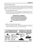
Page 10: ...roper manner OIL AND HAZARDOUS SUBSTANCES The Federal Water Pollution Control Act prohibits the discharge of oil or hazardous substances which may be harmful into U S navigable water Vessels 26 feet in length and over must display a placard at least 5 by 8 inches made of durable material The placard must be installed in a conspicuous place in the rigging compart ments or near the bilge pumps and s...

Page 11: ... your vessel and move away quickly Move your vessel away from the dock and complete a full system check Ensure that electronics pumps and safety equipment are in working order Instruct a passenger on the operation of the boat and the location and function of all safety equipment onboard You should never be the only person capable of safely operating your vessel UNDERWAY INFORMATION ON OPERATION AN...

Page 12: ... Sportfish Cruisers Yachts Owner s Manual for more information and tips concerning anchoring SHALLOW WATER Although your World Cat draws a small amount of water for its size shallow water should be a concern of all boaters To avoid this hazard pay particular attention to navigational markers and know the area you are operating in Be aware of tidal changes including those that have occurred during ...

Page 13: ...CIDENTS Federal regulations require that operators involved in an accident file a written account of the situation within 48 hours Reports should be submitted to the State Boating Law Administrator You can obtain forms through the USCG or local authorities i e harbor patrol sheriff or police offices In the event that a casualty or disap pearance occurs as the result of an accident you must notify ...

Page 14: ...mary concern is the use of generators when boats are moored adjacent to each other Carbon Monoxide is poisonous and potentially fatal if inhaled over an extended period of time Symptoms of CO poisoning include Dizziness Nausea Vomiting Headache Throbbing in the temples Fatigue Muscular twitching Inability to focus or think clearly If you or any of passengers experience any of these symptoms leave ...

Page 15: ...ggish performance a wetter ride and increased bow steering in a following sea In a bow up attitude the boat will perform better but may ride less smoothly Experiment with the trim settings in various sea conditions to determine what you are most comfortable with When using the trim to correct a listing condition imagine an X connecting the starboard engine to the port bow and port engine to the st...

Page 16: ...rsion used in conventional boats For this reason all World Cats are equipped with a hydraulic steering system featuring steering cylinders mounted on each engine and a steering sys tem valve This system enables both engines to respond in unison to adjustments at the helm In order to maintain the excellent steering characteristics of your boat occasionally you will need to adjust the steering syste...

Page 17: ...DESCRIPTION STEERING CYLINDERS KEVLAR PIGTAIL 4 6 KEVLAR STEERING HOSE STEERING SYSTEM VALVE SEA STAR II HELM QUANTITY 2 3 2 1 1 THIS IS A REPRESENTATION OF A TYPICAL WORLD CAT STEERING SYSTEM THE LENGTHS OF THE STEERING HOSES AND PIGTAILS WILL VARY DEPENDING ON THE MODEL YOU HAVE ...

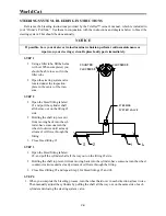
Page 18: ...wheel clockwise until a steady stream of oil flows through the fitting 3 Close bleed fitting 1 STEP 3 1 Open the bleed fitting labeled 2 and pull the cylinder shaft all the way out on the fitting 2 side 2 Holding the shaft to prevent it from moving back into the cylinder have someone turn the wheel counter clockwise until a steady stream of oil flows through the fitting 3 Close bleed fitting 2 and...

Page 19: ...he steering wheel can make a World Cat bite quickly and execute high performance turns Experiment with the han dling ability of your cat so you are prepared for any situation on the water ADVERSE SEA CONDITIONS Catamarans are designed to handle some of the roughest waters in the world but that is no substitute for common sense As an operator you are responsible for the safety of your passengers an...

Page 20: ... to ensuring proper perfor mance but be aware they are not the only factors which affect it Several things which contribute to the level of performance of your catamaran can change between or during trips ENGINE EFFICIENCY Without proper maintenance your engine s will gradually lose power resulting in a loss of speed Use the recommendations in the engine s owners manual to schedule routine mainten...

Page 21: ...istribution to compensate for fuel usage MARINE GROWTH If you store your boat in the water or fail to clean it after each trip the existence of marine growth can contribute to a loss of performance A decline in speed or increased fuel consumption can occur Prevent this by applying a marine growth inhibitor or by cleaning your boat thoroughly after each trip BOTTOM PAINT Bottom painting your catama...

Page 22: ...lation of fuel vapors 3 Extinguish cigarettes or other lighted materials 4 Keep a properly charged and correctly rated fire extinguisher nearby DURING FUELING 1 Use common sense and obey all safety regulations related to fuel handling 2 Avoid static sparks by maintaining contact between the fuel nozzle and fuel fill AFTER FUELING 1 Secure the fuel cap and inspect for leaks 2 Clean up any spilled f...

Page 23: ...u will need to remove the cockpit bol sters by removing the screws that hold it in place To access the screws pull up gently on the bottom of the bolster and locate the drain grommets The factory installs screws in every other grommet to secure the bolster Remove these and pull up and out on the cushion to remove If you experience fuel flow problems remove the fuel feed hose from your engine and c...

Page 24: ...nd parallel batteries in the event of a failure Chapter 5 of this manual will provide details regarding the location and wiring of your batteries and management panel BATTERY DISTRIBUTION The drawing above illustrates the normal operating position for the battery management panel The PORT START STBD START and HOUSE switches as well as the DC MAIN breaker are in the ON posi tion and the EMERG PARAL...

Page 25: ...RALLEL switch 24 HOUR CIRCUITS The push in breakers located across the top of the management panel protect the 24 hour essential circuit wir ing Per NMMA and USCG guidelines these breakers are constantly energized to provide power for bilge pumps and memory functions This helps to protect your vessel even when you are not available The HOUSE switch does not need to be ON for these breakers to have...

Page 26: ... 3 Keep batteries out of the reach of children and pets EXPOSURE If you are exposed to the electrolyte solution follow these procedures and seek immediate medical attention EXTERNAL Flush with large amounts of water for contact with the skin If severe irritation occurs or it con tacts your eyes seek medical attention immediately INTERNAL Consume large amounts of water or milk coupled with milk of ...

Page 27: ...uipped with ATC style blade fuses The lower fuse blocks are connected to the instrument panel on either side of the dash The AC panel in the cabin features residential style cir cuit breakers simply flip to reset Accessories not integrated into the DC dash panels can include lights with integrated switches marine head con trols stereos aftermarket electronics and 12V outlets These devices draw cur...

Page 28: ...d directly into the fuse block SPREADER LIGHTS HARDTOP OPTION ONLY Attached to the hardtop or hardtop frame spreader lights illuminate the cockpit in low light situations They are operated using the switch on the dome light and are protected by the fuse block in the hardtop radio box DOME LIGHT HARDTOP OPTION ONLY Located under the hardtop radio box this light features both white and red lamps for...

Page 29: ...ieve the anchor This accessory is controlled by a dedicated switch at the helm The fuse is located at the battery management panel STEREO OPTIONAL Similar to an automotive stereo the unit can be operated using the faceplate or a remote keypad which is mounted near the helm It is powered by the fuse block and the memory wire is connected to a 24 hour circuit WINDSHIELD WIPER Operated by a switch mo...

Page 30: ...o include a digital hour meter which tracks the amount of time the engine is running Suzuki tachometers include a systems mon itor indicator which features a Low Oil Pressure Warning Engine Temperature Warning Check Engine Warning and Over Rev Limit Warning FUEL GAUGE The fuel gauge displays the remaining fuel level for the tank associated with a given engine TRIM GAUGE Displays the engine trim he...

Page 31: ...World Cat 3 10 ...

Page 32: ...oration resulting from environmental pollutants Use a sponge or other soft cleaning device on the smooth exterior surfaces of the hull and deck A soft brush can be used when cleaning nonskid portions of the deck Make sure to rinse the boat thoroughly after cleaning WAXING Similar to automotive finishes gelcoat will begin to fade over an extended period of time Constant exposure to environmental po...

Page 33: ...ll beneath the water line with anti fouling paint This will help prevent marine growth such as barnacles which damage the gelcoat and affect performance World Cat recommends using an epoxy barrier coat prior to bottom painting a new vessel This will help to prevent but not eliminate gelcoat blistering on the hull which is not warranted by World Cat Your dealer can provide information on bottom pai...

Page 34: ...d aluminum are used throughout your vessel World Cat uses only marine grade stain less hardware and anodized aluminum to provide you with years of service however these metals can deteriorate and fail if improperly cared for Upon returning clean all hardware using a mild detergent and rinse thoroughly with fresh water Avoid using abrasive cleaners or chlorine based products as they will remove the...

Page 35: ...d drains and store the boat with the bow up to allow drainage 3 Inspect all electrical connections and the operation of pumps or other electrical devices Perform repairs if necessary Coat electrical panels with an anti corrosive spray available from your dealer 4 Inspect the batteries and charge fully to prevent damage during storage Disconnect the cables and apply a coat of grease to the terminal...

Page 36: ...water System 5 5 Hosecoil 5 5 Seacocks 5 6 Livewell System 5 6 Raw Water System 5 7 Marine Head 5 7 Initial Start Up 5 8 Normal Use 5 8 Deck Pump Out Procedure 5 8 Overboard Discharge Procedure 5 8 Shorepower Package 5 9 Connecting Shorepower 5 9 Disconnecting Shorepower 5 9 AC Panel 5 9 Refrigerator 5 9 Microwave 5 9 Receptacles 5 10 Stove 5 10 Water Heater 5 10 Battery Charger 5 10 ...

Page 37: ...r 5 12 Teleflex Power Assist Unit 5 12 SYSTEM DIAGRAMS Access Plate and Rigging Tube Diagram 5 13 Hull Wiring Diagram 5 14 Forward Deck Wiring Diagram 5 15 Aft Deck Wiring Diagram 5 16 Cabin Wiring 5 17 Battery Management System Diagram 5 18 Freshwater System Diagram 5 19 Livewell Raw Water System Diagram 5 20 Marine Head Diagram 5 21 Thru Hull Diagram 5 22 ...

Page 38: ...indlass including rope chain and anchor Clarion AM FM Stereo w CD Sirius Satellite Service Fiberglass T Top w Aluminum Frame Electronics Box Rod Holders 6 and Spreader Lights 3 Taco Outriggers 15 or 18 Extended Swim Platform w Ladder Electronic Shift Throttle Controls Fischer Panda 4200 Diesel Generator w 10 gal fuel tank Climate Control System 12000 BTU LCD TV w Integrated DVD player Custom Canva...

Page 39: ...tive side see diagram below The house batteries are wired in parallel and provide the power for all your DC accessories The main lead running to the battery management panel is attached to the starboard house battery The lead connects to the house switch and is routed forward through the 50 amp DC Main breaker located in the top left corner of the management panel During normal operation the DC Ma...

Page 40: ...in a sump is installed in the starboard sponson The sump is equipped with a bilge pump to evacuate grey water overboard and can be accessed using the hatch in the floor of the equipement compartment To gain access remove the bulkhead which divides the head compartment from the equipment room Check the sump at least twice per year to prevent the buildup of waste which could led to clogs more often ...

Page 41: ...ock is open Then install the livewell standpipe When you have completed these steps engage the livewell pump using the switch on the port instrument panel Water will fill the tank until it is level with the standpipe which evacuates water through the hullside To clear bait residue from the tank during operation unscrew the standpipe halfway Two holes cut into the threads of the pipe will allow was...

Page 42: ...n page 15 MARINE HEAD The 320 EC comes equipped with a Vacu Flush marine head in the starboard shower compartment The control panels for the head shown below are located on the vertical wall aft the toilet Power is sup plied to the system through the Tank Watch panel which is feed by a 10 amp fuse located on the acces sory fuse block at the helm The LCD lights on the panel also indicate the level ...

Page 43: ...ge the contents of the holding tank overboard 1 Remove the access plate located behind the head to open the discharge seacock 2 Using the TankMaster panel turn the key switch to manual to engage the macerator pump Hold the key in this position until the Tank Watch panel reads empty 3 Close the discharge seacock and replace the access plate For more instructions on operation winterization and troub...

Page 44: ... distribution panel is installed in the starboard deckwing above the entrance to the aft berth This panel houses the circuit breakers for the AC system and its accessories The panel also contains a reverse polarity indicator Reverse polarity occurs when the AC power lead black and the AC grounded lead white are reversed This can destroy appliances and create the potential for electric shock Theref...

Page 45: ...ngle burner electric stove is provided at the galley Operation is similar to any residental cook top WATER HEATER A six gallon water heater is installed in the equipment compartment aft of the head Temperature is controlled using a thermostat similar to residential water heaters and hot water is provided to the gal ley and shower faucets BATTERY CHARGER Combined with the battery management system ...

Page 46: ... accessory breakers Routine maintenance should be performed on this unit using the guidelines established by Fischer Panda Failure to comply with these guidelines will result in loss of warranty coverage and creates the potential for property damage or personal injury CLIMATE CONTROL UNIT The heating air conditioning unit is mounted under the port lounge seat It can be accessed by remov ing the re...

Page 47: ... and the manufacturer s instruction manual is provided in the Owner s Portfolio detailing its use The circuit breaker for the anchor windlass is mounted on the battery management panel The breaker is connected to the house battery switch If you choose not to have the factory install your windlass World Cat provides wires in the deck harness to allow for aftermarket installs see wiring diagram on p...

Page 48: ...RNER 8 ACCESS PLATE COCKPIT FLOOR 8 ACCESS PLATE MOTORWELL 8 ACCESS PLATE COCKPIT FLOOR 4 ACCESS HATCH EQUIPMENT ROOM AFT INBOARD CORNER 8 ACCESS PLATE CABIN FLOOR CROSSOVER TUBES BATTERY COMPARTMENTS RIGGING TUBES BILGE COMPARTMENT TO BATTERY COMPARTMENT RIGGING TUBES BILGE COMPARTMENT TO BATTERY COMPARTMENT 8 ACCESS PLATE MOTORWELL RIGGING TUBE BATTERY COMPARTMENT TO STARBOARD LOUNGE ...

Page 49: ...World Cat 5 14 HULL WIRING DIAGRAM ...

Page 50: ...World Cat 5 15 FORWARD DECK WIRING DIAGRAM ...

Page 51: ...World Cat 5 16 AFT DECK WIRING DIAGRAM ...

Page 52: ...World Cat 5 17 CABIN WIRING ...

Page 53: ...ense sense house battery port start battery stbd start battery port engine cranking lead stbd engine cranking lead house positive DC MAIN 50A 24 HOUR CIRCUITS to float switches and or memory circuits house negative windlass positive windlass lead windlass breaker ...

Page 54: ...World Cat 5 19 FRESHWATER SYSTEM DIAGRAM ...

Page 55: ...World Cat 5 20 LIVEWELL RAW WATER SYSTEM ...

Page 56: ...World Cat 5 21 MARINE HEAD DIAGRAM ...

Page 57: ...ATER RELIEF SHOWER SUMP OVERBOARD DISCHARGE DRAIN STARBOARD L K J H I H G K L J I N O DESCPRIPTION FISHBOX DRAIN GENERATOR RELIEF FUEL TANK VENT SCUPPERS AFT BILGE BAIT PREP SINK DRAIN D F E C B T HULL A STERN D M FWD BILGE M ANCHOR LOCKER DRAIN N ANCHOR LID DRAIN O LIVEWELL DRAIN WATER TANK VENT COOLER DRAIN AIR CONDITIONER DRAIN S P Q R ...

Reviews: