WDHD3S Kit Assembly Instructions
9
Figs.
7 / 11
FIT THE DIL SWITCHES.
Orientation is important
-
note the
“
on
”
printed on the PCB and
on the switches (the individual switches
“
1
”
and
“
12
”
are also
printed as legends on the PCB). Be very careful when soldering
not to accidentally link across solder points with excess
solder.
FIT ALL THE CAPACITORS.
Note that the electrolytic capacitors C1, C2, C3, C4, C5, C7, C8
are polarized, and ensure they are fitted correctly. The PCB is
printed with a
+
sign where polarity needs to be observed. The
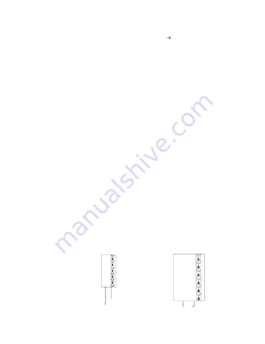
capacitors are normally printed with a white (occasionally black
or gold) bar which denotes the negative terminal as shown below.
FIT THE HEATER LINKS.
We have highlighted the solder points for the heater links in
white on the photograph at Fig. 7 so that you can find them
easily. Note that the links should be fitted to the
solder
side
of the PCB and care should be taken to ensure that the sharp
ends of the components, where they are soldered through the PCB,
do not damage the insulation of the wires. Taking twisted pairs
of brown and grey wire, use the brown wires to connect point
HTR
+
(next to pin HTR
+
OR) to HTR
+
at V2 and onwards to HTR
+
at
V1. Similarly, using the grey wires, connect HTR
-
(next to pin
HTR
-
OR) to HTR
-
at V2 and onwards to HTR
-
at V1.
(
“
HTR
+
”
and
“
HTR
-
”
are, in fact misprints on the PCB
-
the
heaters operate on AC)
-
but the markings make it easier to wire
the heaters of both valves the same way round.)
FIT THE LED.
Solder approx 75
-
100mm red wire to the long leg of the LED and a
similar length of black wire to the short leg. Insulate the
joints and the bare legs of the LED with heat
-
shrink sleeving.
Twist the wires together to provide mechanical stability and
solder the red wire to the LED
+
pin and the black to the LED
-
pin on the PCB. The LED can be passed through the hole in the
chassis ready for fixing to the fascia when you come to do this.
Because access is restricted later, solder approx 100mm red wire
to each of the pins OPL and OPR, and a similar length of black
wire to pins OPLG and OPRG.
(-) negative terminal
(+) positive terminal
(-) negative terminal
(+) positive terminal
Fig. 9
Capacitor Polarity Markings for C4, C5, C7, C8 (left)
and C1, C2, C3 (right)
Fig.10
Figs.
9 / 10


