background image

ECRESO FM 5kW / 10kW, user manual

 11/2021 


Page 165 

WorldCast Systems SAS - 20 avenue Neil Armstrong - 33700 Mérignac (Bordeaux Métropole) FRANCE 
+33 (0)5 57 928 928  

 www.worldcastsystems.com 

 contact@worldcastsystems.com


8.6.4.


Date / Time 

Path: 

System

/Date/Date / Time 


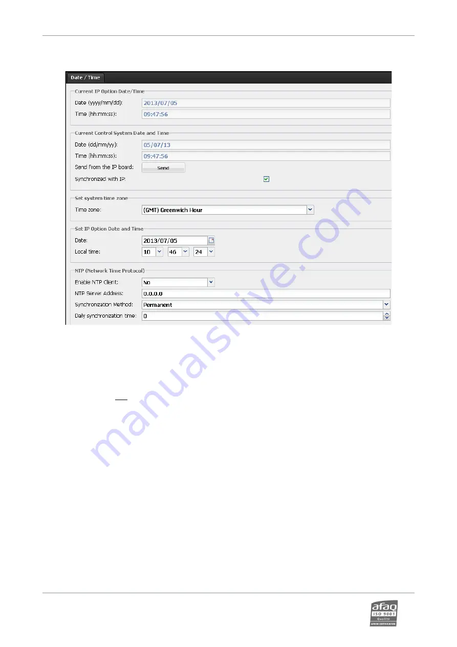
A couple of Ecreso FM internal components are fitted with a clock. This page allows you to make sure they are 
synchronized. The IP board clock can be set on this page: it can manage time zones and will be used as reference for 
the system clock which cannot manage time zone and which is used for RDS. 


Set the time zone 

U

first

U

! Changes in the time zone affect the time that is displayed in the system time window, so 

setting the zone first will eliminate the need to set the system time twice!


System date: 

it can be updated manually by clicking the “Send” button or automatically by checking 

the synchronization box. The IP board time and date is then applied to the system time and date.


Set system time zone: 

The user selects the geographical zone from the list. Important to have this set correctly when using an 
NTP server. 


Set system date:

 the user may update both date (year/month/day) and time (hour/minute/second) 

of the IP board clock.


Network Time Protocol:

 NTP update  

The user can enter a time server address to update the IP board clock automatically. Make sure this 
address can be reached by the unit; specifically, the gateway must be properly set. Specify whether it 
should be synchronized continuously or periodically. For periodic synchronization, indicate what time 
the daily synchronization should occur (between 0 and 23). 


Summary of Contents for ECRESO FM 10kW

Page 1: ...WorldCast Systems web www worldcastsystems com e mail contact worldcastsystems com ECRESO FM 5kW 10kW USER MANUAL 87 5 108 MHz FM TRANSMITTER Date 2021 11 16 Version 2 3 x...

Page 2: ...TE This equipment has been tested and found to comply with the limits for a Class B digital device pursuant to part 15 of the FCC Rules These limits are designed to provide reasonable protection again...

Page 3: ...2 6 1 Front panel 27 2 6 2 Rear panel 28 2 6 3 Opened cover 28 2 7 Exciter Description 29 2 7 1 Front panel 29 2 7 2 Rear panel 29 2 7 3 Opened cover 30 2 7 4 Synoptic diagram 31 2 8 2000 W Power Ampl...

Page 4: ...g or AES inputs 50 4 3 6 Getting on air 51 4 4 With the embedded website 52 4 4 1 Network configuration 52 4 4 2 Connecting to the web interface 52 4 4 3 Configuring the transmitter 53 4 4 4 Sound pro...

Page 5: ...layer 91 6 3 10 MPX Analog 92 6 3 11 MPX Digital 92 6 3 12 Generator 93 6 3 13 Modulation 93 6 3 14 Stereo encoder 93 6 3 15 RDS SCA Encoder 94 6 3 16 Sound Processor 94 6 3 17 RDS 95 6 3 18 Network 9...

Page 6: ...put Selection 150 8 4 7 Input Sources 152 8 4 8 Audio backup configuration 155 8 5 Setting the RDS data 156 8 5 1 Static encoder 156 8 5 2 Dynamic Encoder 158 8 6 System configuration 161 8 6 1 Produc...

Page 7: ...ication of the analog GPIO board 194 10 4 Digital GPIO board with Fault memory 194 10 4 1 Description of control and monitoring functions 194 10 4 2 Remote control function pinout 195 10 4 3 Remote mo...

Page 8: ...dule 228 D 4 Replacing the driver 230 D 5 Replacing a load 231 D 6 Replacing the control unit 232 D 7 Changing the driver fuses 233 D 8 Replacing the control unit battery 234 D 9 Replacing the driver...

Page 9: ...rt of WorldCast Group and employs around 100 people worldwide With its headquarters in Bordeaux France and offices in Miami and Kuala Lumpur the group generates more than 85 of its turnover internatio...

Page 10: ...33700 M rignac Bordeaux M tropole FRANCE 33 0 5 57 928928 www worldcastsystems com contact worldcastsystems com o Simplicity o Product and Service Excellence o Quality ISO 9001 Sustainable Growth o P...

Page 11: ...tioner such as a UPS must be used The device must only be used with a plug that incorporates a protective ground contact To avoid any risk of electrocution the protective earthing conductor must not b...

Page 12: ...nd quick diagnostic for after sale services If missing or if recorded readings show proper operating conditions have not been respected the factory guarantee will be void whether standard or extended...

Page 13: ...verheating VSWR and lightning They also offers a number of built in functions that can eliminate the additional cost and space requirements of external equipment Fully featured for local maintenance a...

Page 14: ...ECRESO FM 5kW 10kW in two different configurations Standard Full Redundancy The transmitter is a 29U rack which includes the following modules ECRESO FM 10kW Standard Full Redundancy Control unit 1 co...

Page 15: ...e Neil Armstrong 33700 M rignac Bordeaux M tropole FRANCE 33 0 5 57 928928 www worldcastsystems com contact worldcastsystems com 2 3 Transmitter front view ECRESO FM 10kW ECRESO FM 5kW 3 amplifiers Ex...

Page 16: ...strong 33700 M rignac Bordeaux M tropole FRANCE 33 0 5 57 928928 www worldcastsystems com contact worldcastsystems com 2 4 Transmitter rear view ECRESO FM 10kW Top to top configuration ECRESO FM 5kW 1...

Page 17: ...n for the following configurations ECRESO FM 5kW Standard version room top ECRESO FM 5kW Full redundancy room top ECRESO FM 5kW Standard version top top ECRESO FM 5kW Full redundancy top top ECRESO FM...

Page 18: ......

Page 19: ......

Page 20: ......

Page 21: ......

Page 22: ......

Page 23: ......

Page 24: ......

Page 25: ......

Page 26: ......

Page 27: ...are ok orange LEDs indicate an issue requiring attention red LEDs indicate a possible loss of transmission Control unit status CPU blinks to indicate CPU activity FAULT major fault of the unit or of...

Page 28: ...ordeaux M tropole FRANCE 33 0 5 57 928928 www worldcastsystems com contact worldcastsystems com 2 6 2 Rear panel 2 6 3 Opened cover GPIO option Mains Exciters communication control Amplifiers and PSU...

Page 29: ...indicate things are ok orange LEDs indicate an issue requiring attention red LEDs indicate a possible loss of transmission CPU blinks to indicate CPU activity FAULT major fault of the unit 3 dB VSWR...

Page 30: ...700 M rignac Bordeaux M tropole FRANCE 33 0 5 57 928928 www worldcastsystems com contact worldcastsystems com 2 7 3 Opened cover Control board Low voltage power bloc Mains filter RF amplifier bloc Con...

Page 31: ...n analog audio input Left and Right Line 2 is a digital input AES 1 connector For an analog mono signal use the left channel Mono for a digital mono signal use the AES input Line 1 is not necessarily...

Page 32: ...MOSFETs This amplifier module is hot pluggable Power is provided by the transmitter s power supply modules 2 8 1 Front panel The lock avoids disconnection of unit during the operation The handle enabl...

Page 33: ...ng 33700 M rignac Bordeaux M tropole FRANCE 33 0 5 57 928928 www worldcastsystems com contact worldcastsystems com 2 8 2 Rear panel Connectors are hot pluggable no screwing or cabling is required 2 8...

Page 34: ...ation The ECRESO FM 10kW includes 6 hot swappable power supply modules or 8 with redundant configuration They providing input current and voltage to the power amplifiers They fit into two 1U chassis T...

Page 35: ...with redundant configuration 1 module with two fans for inlet active redundancy 1 module with two fans for outlet active redundancy Each module has its own power supply and the fan speed is adjusted i...

Page 36: ...e ECRESO FM 10kW and a 3 way coupler for the ECRESO FM 5kW It is a passive and sturdy module It requires no internal cooling On the ECRESO FM 10kW it includes two extractable dummy loads which enable...

Page 37: ...ecifications Cold air taken from the room Hot air evacuated on top Room Top The air inlet must be clear If hot air is evacuated through a pipe longer than 5 m an additional fan is required 927 m3 h an...

Page 38: ...2 13 Roof top 2 14 Hardware options 2 14 1 Mains power on off switch This is a factory option is mounted at the bottom of the cabinet It allows locking the switch in either position with a padlock Fr...

Page 39: ...pole FRANCE 33 0 5 57 928928 www worldcastsystems com contact worldcastsystems com 2 14 2 Emergency stop buttons Two emergency stop buttons can be installed on the front panel on a capping plate and i...

Page 40: ...re protection prevents the transmitter to reach a given reflected power value by blocking the control or by lowering the power Transmitter power 3 kW 5 kW 10 kW Threshold 150 W 200 W 400 W Equivalent...

Page 41: ...in power supply if the difference between the measured voltage and the expected voltage is greater than 10 a Warning alarm is triggered Alarm Volt1 Expected voltage is automatically computed Auxiliary...

Page 42: ...ars Cooling Control unit Internal ventilation fanless FM exciter Between 10 l s and 30 l s depending on ambient temperature 2000W FM amplifier Internal ventilation Fan Max 927 m3 h for each fan module...

Page 43: ...dules filter and dummy load Overall dimension 600 mm x 29U 1390 mm x 1040 mm WxHxD ECRESO FM 5kW Weight 235 kg ECRESO FM 10kW Weight 249 kg 3 4 Interface panel Control unit Indicators Green CPU LED CP...

Page 44: ...on 1 5 Spurious and harmonic suppression 82 dBc 85 dBc 10 MHz input recommended range 10 dBm to 10 dBm 3 6 Composite operation Bandwidth 40 Hz to 53 kHz 0 1 dB 20 Hz to 60 kHz 0 2 dB 60 kHz to 80 kHz...

Page 45: ...Auto adjusted up to 192 kHz Bit 16 24 32 Multiplex MPX SCA Connector BNC Impedance 5 k unbalanced Level Software adjustable 18 18 dBu range 3 10 HF output input FM transmitter output connector 1 5 8...

Page 46: ...ms com contact worldcastsystems com 4 STARTING UP YOUR TRANSMITTER 4 1 Connections 1 Feed the audio input and interlock cables through the cable gland on top of the cabinet and earth the cables on thi...

Page 47: ...down on the control unit and facing left on the drive s 5 Before starting transmitter configuration power the transmitter turn on all switches from left to right on the circuit breaker located on the...

Page 48: ...r up arrow to change the language the Check button to confirm your choice Press the Return button to return to the list of menus 4 3 1 Setting the transmitter Set the power in W the frequency in MHz W...

Page 49: ...d 4 3 6 PLAYER SD card GENE internal generator Use the Check button to switch to edit mode the arrow keys to adjust values and the Check button to confirm Press the Return button twice to return to th...

Page 50: ...tion menu Then press the Check button Browse through the Modulation menu using the arrow keys Set the total MPX deviation between 0 and 150 kHz Set the pilot deviation between 0 and 25 5 kHz For each...

Page 51: ...s only visible in Expert mode you must therefore first change the front panel working mode Press the up or down arrow key until you see the Easy Expert menu Then press the Check button twice Press the...

Page 52: ...Now the transmitter is set connect it to the network Though the web application is compatible with most browsers performances vary from one browser to another For optimal performances Google Chrome i...

Page 53: ...om contact worldcastsystems com The home page displays a synoptic which gives the current status of the transmitter and its parts 4 4 3 Configuring the transmitter Click the button in the tool bar to...

Page 54: ...ed click the button to save the new settings 4 4 4 Sound processing The Sound processing option is enabled for 30 days With an audio input the default preset is 5B Natural To modify sound processing p...

Page 55: ...an to make sure nobody nor any system will control the transmitter during the operation Enable Disable the local mode With the front panel local button The lit yellow LED indicates the unit is in loca...

Page 56: ...g to the priority assigned to the channels and the switching parameters see section 5 5 For the RDS the following inputs can be used see section 5 13 Either set in MPX1 MPX2 or internally Or in auto m...

Page 57: ...case the VSWR is higher than 3 the amplifier power is set to 0 W and again to its set value If the fault is still present the cut restart process is repeated 3 times If the 3rd time it is still presen...

Page 58: ...he on air transmitter or drive is in fault and the other transmitter drive is ready a switch occurs after the delay between fault detection and action has passed default 6 s a delay set accordingly to...

Page 59: ...With this parameter set whether a loss of communication with the main transmitter or drive triggers a switch on ON or OFF 5 6 SmartFM parameters These parameters are available as Front panel SMARTFM...

Page 60: ...otecting from adjacent channels Boost This strategy improves the reception quality while controlling the average power Make sure your transmitter can reach the set power 10 Extreme This strategy achie...

Page 61: ...ority If there is no audio neither on the main source nor on the backup sources or regardless of the priority level the transmitter will remain on or switch back to the main source LINE 1 or 2 MPX PLA...

Page 62: ...ded value 0 to disable the function 2 for optimal results From 0 to 25 5 s FADE IN CONF FADEIN read write With this parameter set the time it will take for the volume to reach its maximum level when a...

Page 63: ...dence on the MPX signal and its sub carrier would be too great or when a 15 kHz filter is already used upstream as with an FM processor for instance In this specific situation you may also use 2 filte...

Page 64: ...ives the composition of the signal on the MPXn input MO mono MO R mono RDS MO R S mono RDS SCA ST stereo ST R stereo RDS or ST R S stereo RDS SCA LEVEL INPUT MPXn LEVEL read write This parameter is th...

Page 65: ...arameters are available as Front panel Generator menu see section 6 3 11 Serial commands INPUT AUDIOGEN see section 7 2 6 Embedded web site Transmitter Input Source Generator page see section 8 4 5 Th...

Page 66: ...ite With this parameter set the maximum audio deviation in kHz generated when the audio source is at the nominal level the nominal level is set with the LEVEL parameter of the menus LINE1 LINE2 MPX1 o...

Page 67: ...ly adjusted with 4 kHz Ex 1 set MPX 75 kHz Pilot 7 5 kHz RDS 4 0 kHz If the RDS is enabled Audio 63 5 kHz Pilot 7 5 kHz RDS 4 0 kHz If the RDS is disabled Audio 63 5 4 67 5 kHz Pilot 7 5 kHz In the ca...

Page 68: ...der menu see section 6 3 13 Serial commands CODER and CONF see sections 7 2 7 and 7 2 4 Embedded web site Transmitter Modulation pages see section 8 4 3 MO ST CODER MOST read write With this parameter...

Page 69: ...e source is MPX1 or MPX2 the transmitter uses the MPX1 or MPX2 as RDS encoder When selecting AUTO the RDS source is updated when there is a switch of audio source OFF disables the RDS MPX1 MPX2 INTERN...

Page 70: ...d write With this parameter set the MPX hard clipper to prevent any possibility of overmodulation on the modulator itself This process is carried out digitally right before the RF generation and is th...

Page 71: ...e these characters will be properly displayed but not in local mode ie the Web interface will show the actual text but not the front panel application CURRENT MAIN RDS DSN This parameter indicates the...

Page 72: ...cal 16 Weather Rhythm and Blues 17 Finance Soft Rhythm and Blues 18 Children s programmes Language 19 Social Affairs Religious Music 20 Religion Religious Talk 21 Phone In Personality 22 Travel Public...

Page 73: ...ynamic 14 stereo with compressed static 15 stereo with compressed dynamic TA TP RDS MAINDSN TATP RDS MAINDSN TA RDS MAINDSN TA read write With this parameter enable or disable the TA Traffic Announcem...

Page 74: ...ses are identified PS Scroll setting available with serial commands the Engi application or with the web site Dynamic data transmission can only be done with the RDS console Setting Commands are avail...

Page 75: ...be one tag keyword frequency or two distinctive tags PROGRAM HOMEPAGE WORS WWWRADIOPAGE Link to radio station homepage Interactivity PHONE HOTLINE The telephone number of the radio stations hotline PH...

Page 76: ...enter RDS PSn CENTER When scrolling is done word by word the encoder may center each word in the receiver screen Only applicable when Word is the chosen increment Increment RDS PSn INCREMENT Set the n...

Page 77: ...Removing and setting it back triggers error messages visible on the embedded web site it should therefore only be done during maintenance operation procedures Unscrew the shield before starting the re...

Page 78: ...values are given in dBr In Absolute mode these values are given in dBu or dBFS and can be positive Input levels affect set thresholds thresholds applied to left and right and to MPX1 and MPX2 can dif...

Page 79: ...RF is ON and the current forward power is below the set 3 dB power threshold The 1 dB can be user set AMBIENT TEMPERATURE ALARM ALARM AMB This alarm is on when the current ambient temperature is above...

Page 80: ...al on the LINE 1 or 2 input The silence detector considers there is no signal accordingly to various user set parameters see section 5 6 LOSS OF AUDIO ALARM ALARM AUDIO LOSS This alarm is on when ther...

Page 81: ...S or a difference between the set SFN delay and the measured SFN delay occurred This alarm indicates a loss of SFN not a loss of transmission POWER SUPPLY UNIT 1 ALARM ALARM SUPPLY1 This alarm is on w...

Page 82: ...rrier of the multiplex signal RDS SCA Encoder to choose the content of the RDS and SCA sub carrier of the multiplex signal RDS to set the RDS Menus are available in both French and English The languag...

Page 83: ...menus are visible above and below the selected menu To display menu parameters press the Check button A scroll bar on the right indicates there are additional parameters use the down arrow to display...

Page 84: ...ems com contact worldcastsystems com To display all menus simply switch to Expert mode Scroll until you see the EASY Expert menu just above the first menu Press the Check button to select it Press the...

Page 85: ...y Forward power synoptic RF Measurements Reflected power VSWR SmartFM SmartFM power Average power Status SmartFM mode MPX Output Deviation Input source Mono Stereo Audio Levels Line1 Left Line2 Left L...

Page 86: ...with dual drive transmitters SMARTFM INPUT SWITCH LINE 1 LINE 2 PLAYER MPX GENERATOR MODULATION STEREO ENCODER RDS SCA Screens and values in orange are only available in Expert mode SOUND PROCESSOR RD...

Page 87: ...VE 2 Only if dual drive PA 1 PA 2 PA 3 PA 4 PA 5 PA 6 PSU 1 PSU 2 PSU 3 PSU 4 PSU 5 PSU 6 PSU 7 Only available with optional additional PSU PSU 8 From the list of menus press the Check key to display...

Page 88: ...ist of menus press the Check key to display the TX Parameters screen Use the arrow keys to display all values Press the Return key to go back to the list of menus 6 3 5 ACU Parameters Acu Parameters O...

Page 89: ...in Expert mode SAVINGS BOOST From the list of menus press the Check key to display the SmartFM screen Use the arrow keys to display all values Press the Return key to go back to the list of menus 6 3...

Page 90: ...Player Idem Line 1 CROSSFADE Crossfade CROSSFADE FADE IN From the list of menus press the Check key to display the Input Switch sub menus Then use the arrow keys to go from one sub menu to the next Us...

Page 91: ...MAX PEAK RIGHT MAX PEAK SAMPLING RATE Only available on AES input From the list of menus press the Check key to display the Line1 or Line2 screen Use the arrow keys to display all values Press the Ret...

Page 92: ...eck button to display the selected sub menu screen Use the arrow keys to display all values Press the Return key to go back to the list of sub menus 6 3 11 MPX Digital The MPX Digital menu is availabl...

Page 93: ...o back to the list of menus 6 3 13 Modulation Modulation values in orange are only available in Expert mode PEAK MPX DEVIATION AUDIO DEVIATION PILOT DEVIATION RDS DEVIATION SCA DEVIATION From the list...

Page 94: ...nus press the Check key to display the RDS SCA screen Use the arrow keys to display all values Press the Return key to go back to the list of menus 6 3 16 Sound Processor Sound Processor Screens and v...

Page 95: ...CURRENT DSN CLOCK TIME ENABLED CLOCK TIME OFFSET DSN MAIN DSN Main ID RT Screens and values in orange are only available in Expert mode PTY PS MS DI TA TP AF LIST RT PTYN GROUPS DSN ALT DSN Alt Idem...

Page 96: ...of menus press the Check key to display the Network screen Use the arrow keys to display all values Press the Return key to go back to the list of menus 6 3 19 Communication ports Communication Ports...

Page 97: ...12V POWER SWITCH POWER DRIVE Drive DRIVE 1 Drive 1 COMMUNICATION STATUS ALARM FAULT ALARM WARNING FORWARD POWER REFLECTED POWER HEATSINK FAN SPEED DRIVE 2 Drive 2 Only available with dual drive trans...

Page 98: ...ist of sub menus 6 3 21 Temperature Fan Temperature Fan AMBIENT TEMPERATURE MAX AMBIENT TEMPERATURE Screens and values in orange are only available in Expert mode LOAD 1 AMBIENT TEMPERATURE MAX LOAD 1...

Page 99: ...NERATE KEY ENTER KEY CLEAR KEY DISABLE LICENSE Disable License ENTER KEY RETURN KEY From the list of menus press the Check key to display the License sub menus Then use the arrow keys to go from one s...

Page 100: ...N HARDWARE VERSION CALIBRATION DATE SERIAL NUMBER UP TIME OPTION LIST VSWR TRIGGER UNIT DISPLAY CLEAR CONFIGURATION SYSTEM RESET LANGUAGE From the list of menus press the Check key to display the Abou...

Page 101: ...g connection set the same communication speed and identical settings for both devices 115200 bits per second 8 data bits No Parity 1 Stop bit No Handshaking Commands may also be used in Telnet when th...

Page 102: ...r LOGIN PASSWORD my_IP_password The password set with the SYS PASSWORD command is not used with remote connections To logout use the LOGOUT command or close the terminal window When disconnecting from...

Page 103: ...AL Allows using drivers which are not managed by the control unit external Warning using an external driver may damage the transmitter ECU SYS FAN_CONFIG R 0 or 1 Indicates the number of fans 0 1 fan...

Page 104: ...n SYS LCDMENUS R W NORMAL or ADVANCED Sets the display type on the front panel screen Easy or Expert ECU DRVn SYS LOCALCOM ECHO R W ON or OFF Adds the local echo on the front panel serial port ECU SYS...

Page 105: ...sible value on the serial port of the unit Comments Module MEAS 5V R xx x x 0 9 Measures the 5 V voltage ECU DRVn MEAS 12V R xx x x 0 9 Measures the 12 V voltage ECU DRVn MEAS 24V R xx x x 0 9 Measure...

Page 106: ...Reads the probe4 temperature in load 2 999 when there is no communication or probe failed ECU MEAS M PKMAX R 150 0 150 0 Absolute value max of the channel M in kHz ECU DRVn MEAS MPXPWR 10S R 320 00 3...

Page 107: ...y loop TX LINK R OPEN or CLOSE State of the CAN bus link TX MODE R LOCAL or REMOTE Single transmitter indicates the local or remote mode TX NAME R W XXXX X A Z Transmitter name TX OPMODE R W ON or OFF...

Page 108: ...ON or OFF Enables disables the Audio Loss alarm for this input Default OFF ECU DRVn CONF AUDIO LOSS SELECT MPXn R W ON or OFF Enables disables the Audio Loss alarm for this input Default OFF ECU DRVn...

Page 109: ...Set the Power from 0 9999 DRVn CONF PWR_MAX R W 0 99999 Set the max power of the transmitter CONF PWR Limited by SYS PAVL DRVn CONF RF R W ON or OFF ON Enable RF OFF Disables RF Warning In external dr...

Page 110: ...No alarm ECU DRVn PAn PSUn ALARM AUDIO LOSS R ON or OFF ON Audio loss Alarm OFF No alarm The alarm is triggered when there is audio loss on all the inputs as set with the commands CONF AUDIO LOSS SELE...

Page 111: ...or OFF ON no signal on the input MPX4 ECU DRVn ALARM OVDR R ON or OFF Indicates whether the input power is too high ON or not OFF PAn ALARM OVDRTRIP R ON or OFF Indicates the overdrive counter has ma...

Page 112: ...INPUT LINE1 ALARM R W NONE or FAULT or WARNING Alarm generated upon loss of signal on the input INPUT LINE1 DRIVE R W 6 00 to 6 00 Drive setting allows an increase of the input audio level without cha...

Page 113: ...R W XXX 0 30 Back delay on the channel with the highest configurable priority INPUT LINE2 SW NOSYNC R W ON or OFF If ON switches on loss of AES synchro INPUT LINE2 SW DELAY R W XXX 1 180 Switching del...

Page 114: ...R 150 150 Gives the deviation max peak value of the transmitted signal in kHz over 100 milliseconds INPUT MPX3 PKMAX R 150 150 Gives the deviation max peak value of the transmitted signal in kHz over...

Page 115: ...N switches on loss of AES synchro INPUT PLAYER SW PRIO R W 0 4 0 disabled Priority of each audio channel 7 highest priority INPUT PLAYER SW SILENCE R W L or R or ANY or BOTH Sets on which channel sile...

Page 116: ...sic 0 speech RDS ALTDSN PI R W XXXX X 0 9 A F Enables RDS to identify the station when searching the frequency using AF or EON AF code RDS ALTDSN PS R W XXXX X 0 9 A Z Station name with 8 characters R...

Page 117: ...default value OTHER RDS INFO SCENE STR R W A Z Sets the command that modifies INFO SZENE default value SCENE RDS INFO SPORT STR R W A Z Sets the command that modifies INFO SPORT default value SPORT R...

Page 118: ...F or TA or TP or TATP Enables disables TA and TP services RDS MMS OTHER STR R W A Z Sets the command that modifies MMS OTHER default value MMSOTHER RDS PHONE HOTLINE STR R W A Z Sets the command that...

Page 119: ...he frame 0 Word RDS PS4 REP R W 0 16 Sets the number of repetition of string1 0 infinite RDS PS4 TEXT R W 0x21 0x7E Dynamically sets the 4th PS scroll line Text with Tags ITEM TITLE ITEM ARTIST RDS PS...

Page 120: ...r or drive ACU OPERATION R W AUTO or MANU Sets the switch to auto or manual switching mode ACU POS R 1 or 2 Gives the switch position ACU PRESELECT R W 1 or 2 Set the main transmitter or drive ACU REA...

Page 121: ...rmocoupler 3 of coupler load 1 ON thermocoupler enabled ECU STAT LOAD2_TEMP1 R ON or OFF State of thermocoupler 1 of coupler load 2 ON thermocoupler enabled ECU STAT LOAD2_TEMP2 R ON or OFF State of t...

Page 122: ...Firefox and enter the transmitter s IP address in the address bar set on the front panel Though the web application is compatible with most browsers performances vary from one browser to another For o...

Page 123: ...edit will always be taken into account After logging the following display pops up if you have less than 30 days or equivalent on a temporary license for the option SmartFM Sound Processor RDS or Act...

Page 124: ...On the right of this bar the frequency the power and the current preset are also indicated The menu on the left allows navigating to the various pages of each section A section may include one or mor...

Page 125: ...dancy The synoptic gives the current status of the transmitter The various elements of the synoptic provide links to the corresponding pages Audio Input Opens the Transmitter Input Select Silence Dete...

Page 126: ...on air fault and error NO SYMBOL unknown on air Power Amplifiers 3 6 opens the Transmitter Maintenance PA Overview page Each sub item opens the Maintenance PA PAn page OK warning fault standby no comm...

Page 127: ...tems SAS 20 avenue Neil Armstrong 33700 M rignac Bordeaux M tropole FRANCE 33 0 5 57 928928 www worldcastsystems com contact worldcastsystems com 8 3 2 Logbook History Recent events Path Status Logboo...

Page 128: ...hanged the VSWR threshold is now set to 1 5 For a list of configuration changes that may appear in the event log please see the Configuration commands section 7 2 4 for Equipment events Sub System col...

Page 129: ...ay also export the log clicking the CSV export button will create the file log_rt csv in you download directory Log History Path Status Logbook History Log History With this page filter events accordi...

Page 130: ...bal efficiency Power amplifier efficiency Drive power max and min synthesis Power amplifier input power max and min synthesis Ambient temperature Heatsink temperature amplifier and PSU max and min syn...

Page 131: ...vel On each curve the button displays the abscissa and ordinate of a specific point Click and drag the abscissa s label to view other points on the curve Curves are displayed in dBr the reference take...

Page 132: ...strong 33700 M rignac Bordeaux M tropole FRANCE 33 0 5 57 928928 www worldcastsystems com contact worldcastsystems com The Audio MPX Spectrum page displays either of the selected curves Path Status Ad...

Page 133: ...ms com The Audio levels page displays the same curve as on the overview page but on a larger scale Path Status Advanced Measurements Audio Levels Red lines the reference level On the MPX outputs graph...

Page 134: ...save the new settings If the transmitter is in local mode orange indicator at the top of the page you will not be able to modify settings 8 4 1 Easy configuration Path Transmitter Easy Config Easy Co...

Page 135: ...FRANCE 33 0 5 57 928928 www worldcastsystems com contact worldcastsystems com Scheduler Scheduler enabled Scheduler off Sound Processor Sound Processor enabled Sound Processor off Switched to Backup M...

Page 136: ...RF parameters on this page Please refer to parameter descriptions section 5 4 for more details Warning In external drive management mode the driver s RF must be enabled before the transmitter s RF to...

Page 137: ...ease refer to parameter descriptions section 5 6 for more details SmartFM is an option If the license is not present the function cannot be enabled Graphs display actual savings and boost as well as u...

Page 138: ...transmitter configuration is associated to the preset RF input and RDS configuration To link a preset to a memory click the button click Rescan to display the content of the card and select the slot...

Page 139: ...om contact worldcastsystems com To manage presets 1 to 6 with GPIOs select 6 inputs Preset Remote Control 1 TC5 2 TC6 3 TC7 4 TC8 5 TC1 6 TC2 To manage presets 1 to 8 with GPIOs select 8 inputs Preset...

Page 140: ...he alarm which will generate the action Up to 10 seconds may be necessary between the time the event is triggered and the time of the action To set which parameters should be modified select a preset...

Page 141: ...lay should not be set On this page set synchronization parameters including SFN parameters Please refer to parameter descriptions section 5 3 for more details Three indicators show Lost synchro No SFN...

Page 142: ...tropole FRANCE 33 0 5 57 928928 www worldcastsystems com contact worldcastsystems com 8 4 3 Maintenance Monitoring Path Transmitter Maintenance Monitoring On this page view the physical state of the t...

Page 143: ...ux M tropole FRANCE 33 0 5 57 928928 www worldcastsystems com contact worldcastsystems com Drive Path Transmitter Maintenance Drive View the physical state of the drive s If the transmitter is in dual...

Page 144: ...ESO FM 5kW 10kW user manual 11 2021 Page 144 WorldCast Systems SAS 20 avenue Neil Armstrong 33700 M rignac Bordeaux M tropole FRANCE 33 0 5 57 928928 www worldcastsystems com contact worldcastsystems...

Page 145: ...0 M rignac Bordeaux M tropole FRANCE 33 0 5 57 928928 www worldcastsystems com contact worldcastsystems com PA Path Transmitter Maintenance PA View the physical state of the amplifiers There is one Ov...

Page 146: ...00 M rignac Bordeaux M tropole FRANCE 33 0 5 57 928928 www worldcastsystems com contact worldcastsystems com PSU Path Transmitter Maintenance PSU View the physical state of the power supply units Ther...

Page 147: ...com 8 4 4 Dual drive This section is only available with dual drive transmitters Switch Path Transmitter Dual drive Switch Set switching parameters on this page Main Reserve Path Transmitter Dual driv...

Page 148: ...ion Path Transmitter Modulation Deviation Set the deviation on this page Please refer to parameter descriptions section 5 13 for more details The equivalent to values set in kHz is displayed Settings...

Page 149: ...ct worldcastsystems com Sound Processor Path Transmitter Modulation Sound Processor Modifications on this page are applied in real time However you must use the Save button to store them permanently S...

Page 150: ...5 57 928928 www worldcastsystems com contact worldcastsystems com 8 4 6 Input Selection Auto Switch Path Transmitter Input Select Auto Switch Set the priority of the various inputs on this page Please...

Page 151: ...ath Transmitter Input Select Silence Detector Set silence detector parameters for various inputs on this page Please refer to parameter descriptions section 5 4 for more details Loss of signal can be...

Page 152: ...e FRANCE 33 0 5 57 928928 www worldcastsystems com contact worldcastsystems com 8 4 7 Input Sources Line 1 Line 2 Path Transmitter Input Source Line 1 or Line 2 Set the analog input Line 1 or the AES...

Page 153: ...tems com contact worldcastsystems com MPX Path Transmitter Input Source MPX Set the MPX 1 and MPX 2 inputs on this page Please refer to parameter descriptions section 5 9 for more details Audio backup...

Page 154: ...l Armstrong 33700 M rignac Bordeaux M tropole FRANCE 33 0 5 57 928928 www worldcastsystems com contact worldcastsystems com Generator Path Transmitter Input Source Generator Set the internal generator...

Page 155: ...kup files are less than 10 Gb To use the audio backup copy up to 20 audio files in wav or mp3 format at the root of a SD card and insert the card in the front panel of the control unit Unscrew the shi...

Page 156: ...updated When values have been changed the button becomes visible click on it to save the new settings If the transmitter is in local mode orange indicator at the top of the page you will not be able t...

Page 157: ...ordeaux M tropole FRANCE 33 0 5 57 928928 www worldcastsystems com contact worldcastsystems com Main DSN Alternate DSN Path RDS Static Encoder Main DSN or Alternate DSN Set DSN parameters on these pag...

Page 158: ...ds if the validity time frame is correct Repetition Then encoder will repeat the line before sending the next one max 99 times Enabled Check the box for the line to be sent Center When scrolling is do...

Page 159: ...collective generally considered responsible for the work ITEM COMPOSITION A complete composition mainly used in classical music ITEM MOVEMENT A movement is a large division of a larger composition or...

Page 160: ...s studio PHONE OTHER Name and telephone number Either as one tag keyword phone number or as two distinct tags SMS STUDIO The sms number of the radio stations studio to send directly a sms into the stu...

Page 161: ...e the new settings If the transmitter is in local mode orange indicator at the top of the page you will not be able to modify settings System parameters modified in the web interface are updated in th...

Page 162: ...the box if line 2 is an MPX input uncheck if line 2 is an audio input When Line 2 is set as a digital MPX input set the MPX 3 and MPX 4 parameters in the Transmitter configuration pages section 8 4 Se...

Page 163: ...contact worldcastsystems com Backing up the transmitter configuration Select the media on which to back up On the PC the backup file is saved on the web browser download directory Its name is FmHp_ve...

Page 164: ...ose to Clone the whole configuration embedded in the unit is restored except for the EMR configuration It can be used to restore a unit after it has been serviced Restore the whole configuration embed...

Page 165: ...st will eliminate the need to set the system time twice System date it can be updated manually by clicking the Send button or automatically by checking the synchronization box The IP board time and da...

Page 166: ...e module select the speed and mode according to the environment choose auto negotiation DNS Servers DNS configuration Mandatory if before using DNS addresses on other configuration pages Authority Cer...

Page 167: ...orldCast Systems SAS 20 avenue Neil Armstrong 33700 M rignac Bordeaux M tropole FRANCE 33 0 5 57 928928 www worldcastsystems com contact worldcastsystems com 8 6 6 Communication Path System Communicat...

Page 168: ...Two web and software accounts are available Administrator Admin admin by default The administrator has full rights Guest Guest guest by default The guest has read only access to all pages except the...

Page 169: ...be set see next section or for test and maintenance Max pending traps set the number of traps in the manager queue between 255 and 1000 MIB to download the MIBs click on the button The mibs zip file...

Page 170: ...be transmitted as SNMPv1 SNMPv2c or Inform SNMPv2c type traps Select the notification type for all traps of a given manager SNMPv1 and SNMPv2c type traps are sent n times Number of repeats before they...

Page 171: ...P address xxx xxx xxx xxx Send mail every enables the user to send messages in a batch every X minutes if desired When waiting for the time chosen by the user the unit stores the messages If the value...

Page 172: ...Product IP address SERIALNUMBER Product serial number FIRSTALARM Name of the 1st alarm If a text address is set the DNS must be configured so as to allow name resolution Make sure the gateway is corre...

Page 173: ...928 www worldcastsystems com contact worldcastsystems com 8 6 12 Traps Emails Path System SNMP SMTP Traps Emails Manufacturer traps are configured like IRT traps see previous section However these tra...

Page 174: ...castsystems com contact worldcastsystems com 8 6 13 License Path System Support License Some options are available either as permanent or as temporary licenses Sound Processor RDS SmartFM and Activati...

Page 175: ...ew presets will keeping the previous ones simply export your old presets before resetting then import selected presets see section 10 3 2 for more information on exporting importing presets To reset S...

Page 176: ...s including key values and associated advices A report over the last month and or week with cumulated values and the last known state of the transmitters A map representation of your network In additi...

Page 177: ...per communication between your transmitter and the EMR server For more information about using EMR please see chapter 11 Local storage of readings Transmitters automatically store data for the after s...

Page 178: ...e next section 8 8 Chatting with other users The icon allows connected users to chat When you click on it the Chat box opens Users are identified by their screen name and their PC IP address Simply ty...

Page 179: ...processing option Unlike many processors there is no bypass preset but a real bypass parameter see parameter description below The presets WB PROTECT and 5B FINALIZE are dedicated to protect your bro...

Page 180: ...esets only available with the Sound processing option 5 band presets Factory Preset Name Description 5 5B FINALIZE A more efficient protection as it uses the 5 band structure configured in a transpare...

Page 181: ...parameters are now available To modify parameters turn the various buttons click on the dot corresponding to the value you want to set or use the scroll wheel when the mouse is over the button Some p...

Page 182: ...pper settings The displayed output level does not take into account the hard clipper 9 4 Sound process parameters BYPASS Unlike several other FM processors the bypass is not a preset but a real bypass...

Page 183: ...can be used to configure a slow or fast gain control Decrease the parameter for purist formats or increase it Boost for commercial formats You should see a real time impact on the AGC vu meter especia...

Page 184: ...g and increased loudness The FIDELITY setting defines how the audio spectrum can or cannot be affected by the processor High values lead to a very natural and purist sound where the bands will also be...

Page 185: ...in drive in dual drive TA off disables the TA basic RDS in simple drive Preselect2 sets drive 2 as main drive in dual drive DSN main enables the main DSN basic RDS in simple drive Auto mode switches t...

Page 186: ...C6 CONF4 10 RC_COMMUN 24 MAIN or AUTO MODE RC7 CONF5 23 RC_COMMUN 24 ALT or MANUAL MODE RC8 CONF6 11 RC_COMMUN 24 Numbers in parenthesis indicated the pin number on the DB25 connector In simple drive...

Page 187: ...mation when configuration is as in the following table Default jumper position Relay Positions Contacts REL_1RT JUMP2 1 2 NO REL2_RT JUMP3 1 2 NO REL3_RT JUMP5 1 2 NO REL4_RT JUMP1 1 2 NO REL6_RT JUMP...

Page 188: ...rldCast Systems SAS 20 avenue Neil Armstrong 33700 M rignac Bordeaux M tropole FRANCE 33 0 5 57 928928 www worldcastsystems com contact worldcastsystems com 10 2 4 Physical representation of the GPIOs...

Page 189: ...ACT R W XX X A F 0 9 Enables the corresponding RM when managed manually see SYS GPIO OUT MASK SYS GPIO IN MASK R W XX X A F 0 9 Sets the RC control either by the control board or manually Hexadecimal...

Page 190: ...IN ACT returns 8A You must convert the hexadecimal value in binary ie 8A 10001010 which indicates that RC 2 4 and 8 are activated To control RM 3 and 5 convert the binary value 00010100 you get 14 as...

Page 191: ...mode VSWR indicates if there is a VSWR error 10 3 2 Remote control function pinout Function Remote Control Input name Common POWER ON RC1 OPT1 20 RC_COMMUN 24 POWER OFF RC2 OPT2 8 RC_COMMUN 24 RF ON...

Page 192: ...EL5_T 18 REL5_C 6 OFF ou PRESELECT 2 RM6 REL5_R 5 REL5_C 6 VSWR RM7 REL6_RT 19 REL6_C 7 Numbers in parenthesis indicated the pin number on the DB25 connector Default configuration for ACU A closed lin...

Page 193: ...l Armstrong 33700 M rignac Bordeaux M tropole FRANCE 33 0 5 57 928928 www worldcastsystems com contact worldcastsystems com 10 3 5 Physical representation of the analog GPIOs 12 V floating power suppl...

Page 194: ...wer W 20 50 50 50 100 100 200 200 300 300 600 Ambient temperature C 70 70 70 70 70 70 70 70 70 70 70 Fan speed rpm 19000 19000 6000 6000 6000 6000 19000 19000 19000 10000 10000 Voltage 1 Voltage 2 V 6...

Page 195: ...linked to the internal working of the transmitter temperature voltage Fault indicates a transmitter fault 10 4 2 Remote control function pinout Function Remote Control Input name Common POWER ON RC1 S...

Page 196: ...J17 REL5 FAULT 2 3 TRAVAIL 1 2 NO J2 Statut Commun 1 2 V 2 3 NO J9 REMOTE_COM 2 3 MASSE 1 2 rel_remote_com J10 RF_OFF_COM 2 3 MASSE 1 2 rel_rf_off_com J16 FAULT_COM 2 3 MASSE 1 2 rel_fault_com J12 ST...

Page 197: ...s SAS 20 avenue Neil Armstrong 33700 M rignac Bordeaux M tropole FRANCE 33 0 5 57 928928 www worldcastsystems com contact worldcastsystems com Default jumpers positions Jumpers are normally open for r...

Page 198: ...avenue Neil Armstrong 33700 M rignac Bordeaux M tropole FRANCE 33 0 5 57 928928 www worldcastsystems com contact worldcastsystems com 10 4 4 Physical representation of the digital GPIO with Fault memo...

Page 199: ...SYS GPIO OUT ACT R W XX X A F 0 9 Enables the corresponding RM when managed manually see SYS GPIO OUT MASK SYS GPIO IN MASK R W XX X A F 0 9 Sets the RC control either by the control board or manuall...

Page 200: ...he following table Hexadecimal Binary 0 0000 1 0001 2 0010 3 0011 4 0100 5 0101 6 0110 7 0111 8 1000 9 1001 A 1010 B 1011 C 1100 D 1101 E 1110 F 1111 Examples If the command SYS GPIO IN ACT returns 8A...

Page 201: ...key will be created which will unblock the desired option The last step will be to send it to the transmitter This activation process can be done using the embedded web site the front panel applicatio...

Page 202: ...u and press the Check button Press the Check button again to generate the key for your transmitter Send the serial number and the key to WorldCast Systems A new key will be returned to you To enter th...

Page 203: ...The return value will have the following format serial_number key1 Send this key to WorldCast Systems A new key will be returned to you serial_number key2 Once you have received the new key send the c...

Page 204: ...FRANCE 33 0 5 57 928928 www worldcastsystems com contact worldcastsystems com APPENDIX B ADJUSTING THE IMPEDANCE OF ANALOG INPUTS Default impedance of analog inputs is high It can be set to 600 by ju...

Page 205: ...on we recommend you use Google Chrome or alternatively Google Chrome Portable which can work without being installed on your PC it can be on a flash drive As a first time user you will have to set you...

Page 206: ...red to set the transmitters C 1 3 Setting up transmitters Connect to the embedded web site of your transmitter and display the System Support Advanced Logging page Enter its position and your EMR acco...

Page 207: ...33 0 5 57 928928 www worldcastsystems com contact worldcastsystems com C 2 Using EMR C 2 1 Presentation Connect to the EMR site again using your login and password A tool bar gives you access to the...

Page 208: ...be optimized Transmitter in nominal state The status of the transmitter is determined by alarms visible on the Dashboard In case there several events are occurring at once the status will be that of...

Page 209: ...epending on the transmitter power 5 kW 10 kW Forward power 0 6000 W 0 12000 W Reflected power 0 500 W 0 1000 W Mosfet efficiency 0 100 Global efficiency 0 100 And the following readings Mosfet current...

Page 210: ...0 2000 hPa Auxiliary Power supply X X Main Control Board Temperature 0 125 C 0 125 C Main Control Board Temperature alarm Threshold 65 C Threshold 65 C Current Power Supply Output 0 420 A 0 420 A Dig...

Page 211: ...00 V 0 300 V Voltage Power Supply Output 0 70 V 0 70 V VSWR 1 5 1 5 All values are given in real time For parameters followed by a in the table values are logged and a time graph can be displayed by c...

Page 212: ...own account and to set the transmitters On the user configuration page set the notifications you would like to receive by email by checking monthly and or weekly report Reports can also be downloaded...

Page 213: ...CRESO FM 10kW 2000 W FM amplifier 6 around 13 kg PSU between 6 and 8 around 2 5 kg Dummy load module 2 around 19 kg Rack with exciter s control unit filter 1 around 277 kg Rear panel Slot filler Fan f...

Page 214: ...castsystems com contact worldcastsystems com D 2 Unpacking the cabinet If your transmitter came in a simple crate for road transport unpack the elements and go to section C 3 Using a drill set on low...

Page 215: ...WorldCast Systems SAS 20 avenue Neil Armstrong 33700 M rignac Bordeaux M tropole FRANCE 33 0 5 57 928928 www worldcastsystems com contact worldcastsystems com Remove the 6 screws off panel 4 Remove th...

Page 216: ...021 Page 216 WorldCast Systems SAS 20 avenue Neil Armstrong 33700 M rignac Bordeaux M tropole FRANCE 33 0 5 57 928928 www worldcastsystems com contact worldcastsystems com Remove the 8 screws off pane...

Page 217: ...e FRANCE 33 0 5 57 928928 www worldcastsystems com contact worldcastsystems com Remove the protective film wrap with a knife Make sure to not scratch the cabinet Unscrew the 4 brackets from the cabine...

Page 218: ...on the configuration the connector panel is available either through the rear door or on the front of the cabinet The label High Voltage on the cabinet shows the exact location of the connector panel...

Page 219: ...il Armstrong 33700 M rignac Bordeaux M tropole FRANCE 33 0 5 57 928928 www worldcastsystems com contact worldcastsystems com With front panel connector The transmitter is cabled for three phase power...

Page 220: ...28 www worldcastsystems com contact worldcastsystems com The supplied cable can be directly connected to the mains You may also use your own cable which will need to hooked to the connector panel cabl...

Page 221: ...Top configuration Connect the lower fan block 9 pin plug SP02170 D to the fan cable SP02142 before screwing the fan block to the cabinet ECRESO FM 10kW only connect the Dummy Load 2 D sub 9 pin cable...

Page 222: ...ems com contact worldcastsystems com Connect the Dummy Load 1 D sub 9 pin cable at the rear of the Dummy Load 1 SY01370 A0 before inserting the load in the 3 RF connectors at the top of the combiner T...

Page 223: ...ly units AL00122 in the slots PSU1 to PSU6 on the front lower part of the cabinet Before inserting the PSU press the lock on the bottom left to unlatch the front screen and open it Close it when the P...

Page 224: ...x M tropole FRANCE 33 0 5 57 928928 www worldcastsystems com contact worldcastsystems com D 5 RF connection Remove the 6 screws that hold the filter mounting plate on the cabinet rooftop Disconnect th...

Page 225: ...28 www worldcastsystems com contact worldcastsystems com Insert the rigid line make sure to keep the seal in place Connect the antenna to the RF output 1 5 8 flange connector Screw the mounting plate...

Page 226: ...maintenance operations requiring the chassis to be open ESD work space and protections are necessary To order spare parts please contact your WorldCast Systems dealer E 1 Replacing a power supply uni...

Page 227: ...ifier Amplifier reference EF01204 Amplifiers are hot swappable If the faulty amplifier is not replaced right away a dummy amplifier must be put in its place The dummy amplifier supplied by WorldCast S...

Page 228: ...ed out Quickly replace the fan module to avoid triggering the temperature safety Top fan module Fan module reference SP01984 S or SP01984 D for redundant systems Unlock both bottom locks then both top...

Page 229: ...ESO FM 5kW 10kW user manual 11 2021 Page 229 WorldCast Systems SAS 20 avenue Neil Armstrong 33700 M rignac Bordeaux M tropole FRANCE 33 0 5 57 928928 www worldcastsystems com contact worldcastsystems...

Page 230: ...st be identical to the transmitter s version Open the rack on the front of the cabinet Turn off the faulty driver using the rear panel switch Disconnect all cables power supply and ground audio inputs...

Page 231: ...he transmitter needs to be off air Load reference SY01370 A0 Unlock both bottom locks then both top locks of the rear panel to remove it Unplug the cable off the faulty load Pull out the load Before s...

Page 232: ...the front of the cabinet Turn off the faulty control unit using the rear panel switch Disconnect all cables Remove the faulty control unit and replace it Reconnect all cables except for the driver an...

Page 233: ...ce FXE00019 Fuses are located in the power socket on the rear panel Insert a flat screwdriver below the red line of the switch on the left side and pull lightly outward The fuse module will come out T...

Page 234: ...57 928928 www worldcastsystems com contact worldcastsystems com E 8 Replacing the control unit battery Battery reference AL00043 See the control unit replacement procedure above D 7 to remove the cont...

Page 235: ...rldcastsystems com contact worldcastsystems com E 9 Replacing the driver battery Battery reference UXE00227 See the driver replacement procedure above D 4 to remove the driver from the cabinet Unscrew...

Page 236: ...4 screws off the cover and slide it towards the rear as described above D 9 In order to make the operation easier you may also dismount the front panel remove the 7 screws of the front panel Remove th...

Page 237: ...rignac Bordeaux M tropole FRANCE 33 0 5 57 928928 www worldcastsystems com contact worldcastsystems com Put the supply cable in the insert and connect the supply cable Reset the baseplate Set the fron...

Page 238: ...e air filters Drive air filter reference SP01799 A0 Bottom fan block air filter reference SP01919 Power supply air filter reference SP01858 Optional air filters can be set on the driver front panel Ov...

Page 239: ...e a defective audio board or to replace the analog audio board by an AES board In the standard configuration the transmitter is fitted with One analog audio board Line 1 One AES board Line 2 1 See the...

Page 240: ...panel cutouts and then connect it to the commutation board 6 Screw the 2 or 4 screws on the rear panel 7 Screw the lid back in place If you have replaced the analog audio board by an AES board 8 Set t...

Page 241: ...calibration is kept After a configuration reset we recommend you check parameters meant to protect the transmitter hard clipper activation deviation and VSWR Trip Connect a PC to the front panel seri...

Page 242: ...port Firewalls are usually not restricting outgoing connections so no specific changes have to be done DNS access is also required to reach the EMR server but as a common service DNS protocol is almo...

Page 243: ...dcastsystems com contact worldcastsystems com FOR MORE INFORMATION Please contact Head office WorldCast Systems 20 avenue Neil Armstrong 33700 M rignac Bordeaux M tropole FRANCE Tel 33 0 557 928 928 H...

Reviews: