ECRESO FM 5kW / 10kW, user manual
–
11/2021
Page 40
WorldCast Systems SAS - 20 avenue Neil Armstrong - 33700 Mérignac (Bordeaux Métropole) FRANCE
+33 (0)5 57 928 928
–
www.worldcastsystems.com
–
contact@worldcastsystems.com
2.15.
Protecting the transmitter
To ensure the transmitter will work with no risk of damage, a series of protections has been set.
2.15.1.
Surge Protector
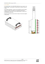
An optional surge protector module can be added. The goal of this module is to limit the surge caused by lightning.
The protector principle is to capture the surge and divert it to the ground so as to protect the transmitter and its
power supplies.
The surge protector used by WorldCast Systems includes multi-MOV technology and a gas discharge tube (GDT) giving
a very high protection and very low parasitic capacitance and leakage currents.
2.15.2.
Protection against VSWR
Several systems coexist to offer the optimal protection against VSWR:
•
Hardware protection:
In case of open circuit or short-circuit, the RF is cut. When the situation returns to normal, it is automatically
reset. The protection is triggered in case of an overshoot of the reflected power over:
Transmitter power
3 kW
5 kW
10 kW
Threshold
300 W
300 W
600 W
Equivalent VSWR at nominal power
1.92
1.65
1.65
Hardware protection is also present for the 100 W drive at 28 W
•
Software protection:
The software protection prevents the transmitter to reach a given reflected power value by blocking the
control or by lowering the power.
Transmitter power
3 kW
5 kW
10 kW
Threshold
150 W
200 W
400 W
Equivalent VSWR at nominal power
1.57
1.50
1.50
Software protection is also present for the 100 W drive at 15 W, and for the preamplifiers.
•
Software settings for the reflected power security management: if the VSWR is greater than 3 in a recurring
way, enabling the VSWR Trip parameter allows disabling then cutting the RF (see VSWR Trip, section 5.4).
2.15.3.
Protection against high temperature
The ambient temperature and the heatsink temperature are monitored.
•
The max ambient temperature is set by software, default value is 60°C for the amplifier and 50°C for the control
unit. In case of overshoot, a Warning alarm is triggered (Alarm Amb). The default value works when the room
temperature is controlled. In case the room temperature is likely to be greater than 35°C, the value should be
increased accordingly, but should not exceed 70°C.
•
The max heatsink temperature is set by serial command (see serial command CONF.HEAT.MAX, section 7.2.4),
default value is 80°C. In case of overshoot, a Warning alarm is triggered (Alarm Heat).
•
The max heatsink temperature is set at 90°C. If the temperature exceeds 90°C, the RF is cut off and a fault
alarm is triggered (Alarm Temp).
2.15.4.
Protections incorporated into the control unit and exciter PSU
The control unit and exciters have an auxiliary power block and a power block, each having its own protections:


