ECRESO FM 5kW / 10kW, user manual
–
11/2021
Page 27
WorldCast Systems SAS - 20 avenue Neil Armstrong - 33700 Mérignac (Bordeaux Métropole) FRANCE
+33 (0)5 57 928 928
–
www.worldcastsystems.com
–
contact@worldcastsystems.com
2.6.
Control Unit description
The Control Unit manages:
•
the exciter(s)
•
the power amplifiers
•
the power supplies
•
the cooling modules
•
the RF coupling
•
the output power
2.6.1.
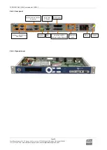
Front panel
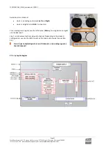
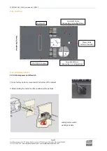
Description of indicator LEDs:
As a rule, green LEDs indicate things are ok, orange LEDs indicate an issue requiring attention, red LEDs indicate a
possible loss of transmission.
Control unit status:
•
CPU: blinks to indicate CPU activity
•
FAULT: major fault of the unit or of the transmitter
•
WARNING: minor fault of the unit or of the transmitter. For dual-drive system, it can
also represent a switching issue.
•
RF: indicates that the unit is on RF=ON. Associated to the RF button.
•
LOCAL: indicates that the unit is in local mode. Associated to the Local button
Indicators: CPU,
Fault, Warning
RF monitoring output
RF on/off and local
mode buttons and
LEDs
Navigation
buttons
Display
RJ45 port for console, USB port
(internal use) and µSD card

