Operation—Operator's Station
DB84312,0000026 -19-09JAN12-1/1
OUT4001,0000747 -19-11JAN11-1/1
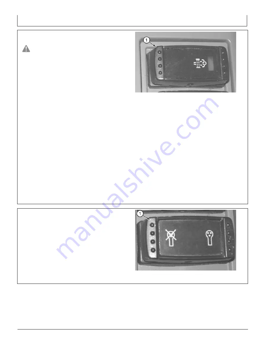
Exhaust Filter Parked Cleaning Switch
CAUTION: Servicing machine during exhaust
filter parked cleaning can result in serious
personal injury. Avoid exposure and skin contact
with hot gases and components.
During exhaust filter parked cleaning, the engine
may run at elevated idle and hot temperatures
for an extended period of time. Exhaust gases
and exhaust filter components may reach
temperatures hot enough to burn people and
ignite or melt common materials.
Avoid death or serious injury from machine
movement. Do not leave running machine
unattended during exhaust filter cleaning.
IMPORTANT: Avoid machine damage. Always
park machine in a safe location and check
for adequate fuel level before beginning
exhaust filter parked cleaning.
The exhaust filter parked cleaning switch (1) is located
on the right console.
Before starting the parked cleaning process, the machine
needs to be in a predetermined safe state. This safe state
includes three conditions:
•
Machine is parked in a safe place with the front
attachment lowered to the ground
•
Pilot shutoff lever is in locked (UP) position
•
Engine speed dial is set to slow idle
An exhaust filter alarm indicator will appear on the monitor
to inform the operator when a parked cleaning needs to
TX1086795A
—UN—1
1JAN1
1
Exhaust Filter Parked Cleaning Switch
1— Exhaust Filter Parked
Cleaning Switch
take place or the operator can check the restriction level
bar graph in the monitor. See Main Menu—Information
Menu—Monitoring. (Section 2-2.)
Once the safe state conditions are met, press and hold
the right half of exhaust filter parked cleaning switch for 3
seconds to begin a parked cleaning procedure.
Monitor will show a progress screen during the cleaning
and will prompt the operator when the cleaning is
complete.
For more information, see Exhaust Filter Parked Cleaning.
(Section 2-3.)
Right Enable Switch
The right enable switch (1) is located on the right console.
Press right half of switch to enable auxiliary functions on
the right pilot control lever.
Press left half of switch to disable auxiliary functions on
the right pilot control lever.
1— Right Enable Switch
TX1086796A
—UN—1
1JAN1
1
Right Enable Switch
2-1-7
092221
PN=66
Summary of Contents for 380GLC
Page 6: ...Introduction Continued on next page TX JDEULA 19 11JUL16 2 3 TX1219046 UN 11JUL16 092221 PN 6...
Page 7: ...Introduction TX JDEULA 19 11JUL16 3 3 TX1219047 UN 14JUL16 092221 PN 7...
Page 9: ...Introduction DX EMISSIONS EPA 19 12DEC12 2 2 TS1721 UN 15JUL13 092221 PN 9...
Page 17: ...Introduction DX EMISSIONS CARB 19 26AUG20 8 8 RG32759 UN 19AUG20 092221 PN 17...
Page 24: ...Introduction 092221 PN 24...
Page 287: ...Index Index 11 092221 PN 11...
Page 288: ...Index Index 12 092221 PN 12...


