31
CS200
Control Systems
Controller
Operation
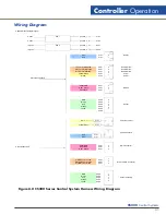
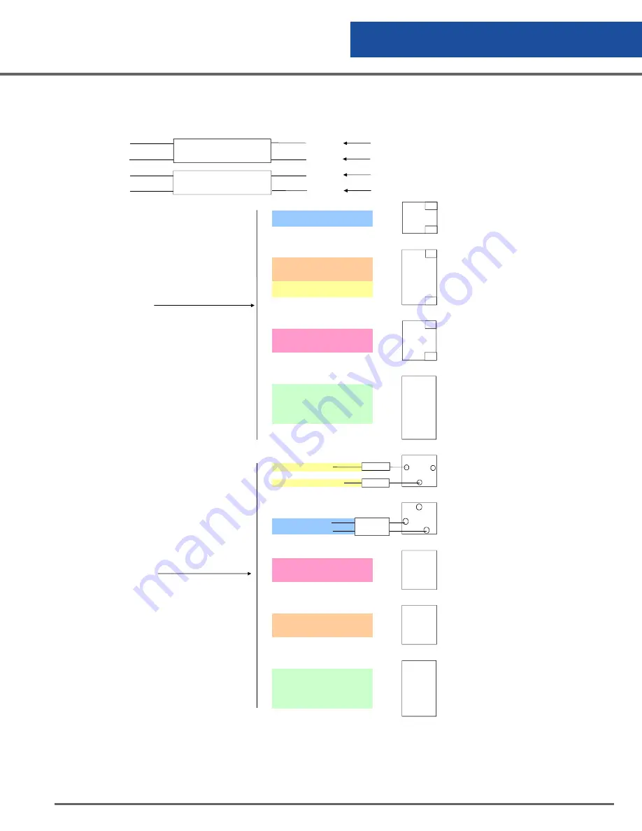
Wiring Diagram
CS200 Harness Wiring Diagram
4 wires
position 1
P1P1
4 wires
position 2
P1P2
10 wires
position 1
P2P1
10 wires
position 2
P2P2
Blue
P1P1
Battery
Red
P1P1
White/Yellow
P2P1
Remote Alarm
White/Orange
P2P1
Remote Alarm
Brown + White/Brown
P2P1
Remote Alarm
Yellow/Green
P1P1
Power
White
P1P1
Power
Harness Control End
White/Black
P2P1
Red + Black
P2P1
RS-232
White/Red
P2P1
Black
P2P2
Brown
P2P2
Red
P2P2
Sensor
Orange
P2P2
Yellow
P2P2
P2P2
white
Power Connector
Yellow/Green
Valve Connector
Red
Blue
White/Black
P2P1
DB-9 Connector
Connector Box End
White/Red
P2P1
Red + Black
P2P1
White/ Yellow
P2P1
White/ Orange
P2P1
Remote Alarm Connector
White/Brown + Brown
P2P1
Black
P2P2
Brown
P2P2
Red
P2P2
Sensor Assembly
Orange
P2P2
Yellow
P2P2
Pod 1
Pod 2
2
1
5
4
3
2
1
3
2
1
6
5
4
3
2
1
P1P1
P1P1
P1P1
P1P1
2
3
5
1
2
3
1
2
3
4
5
Figure 8.0 CS200 Series Control System Harness Wiring Diagram
White
Summary of Contents for CS200
Page 2: ......

