39
CS200
Control Systems
Removing/Installing the Solenoid Valve
The LN
2
and power must be turned off before beginning work on the solenoid valve.
For LABS Electrical Units
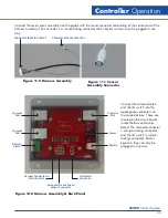
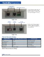
Disconnect the solenoid valve lead connection from the back of controller board.
To remove the solenoid valve, loosen the compression fitting that connects the plumbing tubing to the fill tube.
Remove the two (2) mounting screws that hold the solenoid valve to the solenoid bracket. Remove the solenoid
valve and its associated plumbing. Disconnect the plumbing from the inlet and outlet side of the solenoid valve.
To install a new solenoid valve, attach the compression fitting to the fill tube then connect the compression fitting
to the elbow connected to the outlet side of the solenoid valve. Use Teflon tape (three wraps) on all threaded.
Attach the compression fitting to the fill tube first and then connect the compression fitting to the elbow that is
connected to the outlet side of the solenoid valve. Position the solenoid valve onto the solenoid valve bracket
and reattach and tighten the two (2) mounting screws. Attach the solenoid valve lead connection to the
controller board.
Removing/Installing the Controller 10K/24K Units
Remove the cabinet top, follow the steps illustrated in Figure 17. Remove two (2) screws from the display and
lift it from the refrigerator far enough to detach its electrical connection wiring. Remove four (4) screws from the
top of the refrigerator and lift the cabinet top to gain access to the area between the cabinet and the insulated
inner vessel. On the 10K and 24K, the cabinet top may only be raised as shown because of the lid hinges.
Do not remove the hinged lid.
After the cabinet top is loosened and propped up, the electrical
connection wiring may be detached to allow access to its back panel connection. At the completion of
maintenance or repairs, reattach the electrical connection wiring from the controller to the display.
Ice or frost in the sensor tube may restrict the movement of sensor probes in the tube. Do not pull excessively on
the sensor wiring while attempting to remove sensors. It may be necessary to remove the sensor tube from the
container and allowed it to thaw before the sensors can be removed.
To install the controller, install the electrical supply connections panel to the back of the refrigerator. Feed
the wiring harness from the electrical supply connections panel to the front of the refrigerator and through
the opening to where the display will be mounted. Attach the electrical supply connections to the controller
board. Be sure to follow all of the installation procedures for the thermocouple, sensor probes and solenoid
valve before you reattach the cabinet top. Reattach the cabinet top with the (4) four screws that were removed
(See Item 2 of Figure 16.0) out to remove the cabinet top. Carefully lower the display into the cabinet. Attach
the display to the cabinet top with the (2) two supplied screws. Be sure that all of the necessary installation
procedures have been completed before you start to fill the refrigerator. To start filling, refer to Filling the
Refrigerator (Initial Fill) section of this manual.
Controller
Operation
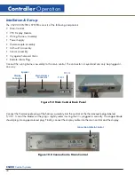
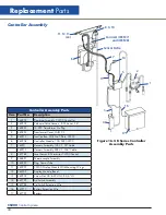
Figure 15.0 K Series Controller Removal
Summary of Contents for CS200
Page 2: ......

