background image

55

CS200

 Control Systems

Cryowire

Network

Cryowire

Network

Cryowire

  Local


Power

12 VDC, 3A

Remote

  Alarm

Battery

12V, 2.5A

NO

C

NC


 4075 Hamilton Blvd.

            Theodore, AL 36582


       WorthingtonIndustries.com

+

-

844-273-7517 / +1 614-438-7968

Warranty

Worthington Industries warrants that each of its electronic controllers and displays will be free from defects in 

material and workmanship, in the normal service for which the product was manufactured, for a period of two 

(2) years from the original date of purchase. Worthington Industries at its option will either repair or replace any 

item covered under this warranty.

This warranty is void if the product is used for any other purpose than that for which it was designed, including 

but not limited to connection with third party systems. This warranty is void if the product is in any way altered 

or repaired by others. Worthington Industries and/or its suppliers shall not be liable under this warranty, or  

otherwise, for defects caused by negligence, abuse or misuse of this product, corrosion, fire or the effects of 

normal wear.
The remedies set forth herein are exclusive. Worthington Industries shall not be liable for any indirect or  

consequential damages including, without limitation, damages relating to lost profits or loss of products,  

resulting from the delivery, use or failure of the product or for any other cause. By accepting delivery of the 

product, the purchaser acknowledges that this limitation of remedies is reasonable and enforceable. In no  

case shall Worthington Industries’ liability exceed the purchase price for the product.

Appendix

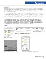
Figure 17.0 

Main Rating Label

Figure 17.1 Control & Display Label

Figure 17.2 Connector Box Label

Figure 17.3 Battery Label - (Optional)

Labels

Summary of Contents for CS200

Page 1: ... UNDERSTAND THESE INSTRUCTIONS DO NOT PERMIT UNTRAINED PERSONS TO USE OR MAINTAIN THIS UNIT IF YOU DO NOT FULLY UNDERSTAND THESE INSTRUCTIONS CONTACT YOUR SUPPLIER FOR FURTHER INFORMATION BEFORE ATTEMPTING TO OPERATE THIS CONTROLLER WITH ANY WORTHINGTON INDUSTRIES LABS OR K SERIES UNITS YOU MUST READ THE SEPARATE OPERATING AND SAFETY MANUAL PROVIDED WITH THAT UNIT CS200 Control Systems LABS and K ...

Page 2: ......

Page 3: ...c Compatibility EMC 11 Power Supply Connection 12 Validation 12 OPERATION 13 Initial Fill 13 Control Components 13 CS200 Controller Display Guide 14 Operational Theory 14 Alarm Conditions 15 Lid Switch 16 Solenoid Valve 17 Thermocouples 17 Power Supply 17 Remote Alarm 17 Operating Parameters 17 Temperature Monitoring 18 Liquid Phase Storage 18 Maintenance 18 CONTROLLER OPERATION 20 Introduction 20...

Page 4: ...moving Installing the Sensor Probes 40 Making Adjustments to the Level Settings 40 Removing Installing the Solenoid Valve 41 REPLACEMENT PARTS 42 Plumbing Assembly 42 Controller Assembly 43 TROUBLESHOOTING 45 Symptoms 45 Controller Will Not Turn ON 45 High Liquid Level 45 Indicates Low LN2 Supply 46 Indicates Open Sensor 46 Temperature Reading 10 to 20 Warm 46 Fill Solenoid Cycles On and Off 47 So...

Page 5: ...er operating pressures will increase transfer losses and create excessive turbulence of the liquid in the freezer which can generate false signals to the liquid level controller causing the freezer to under fill In liquid phase storage applications excessive turbulence can cause splashing which could result in personal injury and or damage to the freezer When installing piping or fill hose assembl...

Page 6: ...d to work with Worthington Industries Cryostorage Systems The features are designed to provide a safe environment for samples while at the same time tracking all relevant information associated with the freezer This control provides a complete historical record of the environment in your unit and therefore the environment in which your samples have been stored in this system This controller featur...

Page 7: ... 1o C Number of channels 2 Temperature Display Units o C F K R Electrical Input Voltage 100 240 VAC Input Current max 1 75 A Input Current continuous 5 A Power Consumption max 21 W Power Consumption continuous 6 W Input Frequency 50 60 Hz Output 12 VDC Control Input Voltage 12 VDC Power cord Available for all countries Battery Rating 12 Volt 18Ah Type AGM Sealed Non Spillable Short Protection Inst...

Page 8: ...r Alarm Always enabled High Temperature Alarm T C 1 T C 2 Programmable Low Temperature Alarm T C 1 T C 2 Programmable Thermocouple Calibration Alarm Always enabled Thermocouple Open Alarm Always enabled Power Failure Remote only Always enabled Low LN2 Supply Alarm Programmable Battery Mode Warning Always enabled Lid Open Too Long Alarm Programmable Valve Stuck Open Alarm Programmable Unauthorized ...

Page 9: ...al menu Data Collection Temperature Yes Level Yes Alarms Yes Memory 4 Mb Dimensions Display Width 9 5 241 mm Display Height 2 0 50 8 mm Display Depth 1 31 33 3 mm Display Weight 625 lbs 28 kg Main Control Width 8 875 225 4 mm Main Control Height 6 688 169 9 mm Main Control Depth 1 25 4 mm Main Control Weight 1 0 lbs 45 kg Battery Width 7 25 184 2 mm Battery Height 6 375 161 9 mm Battery Depth 3 25...

Page 10: ...gton Industries immediately Worthington Industries cannot be responsible for any missing parts unless notified within 10 days of shipment Freight Damage Procedures Any freight damage claims are your responsibility Cryostorage Systems are delivered to your carrier from Worthington Industries dock in new condition when you receive our product you may expect it to be in that same condition For your o...

Page 11: ...eclarations regarding EMC for the CS200 SERIES Control System The CS200 SERIES Control System needs special precautions regarding EMC and needs to be installed and put into service according to the EMC information provided in the following pages Portable and Mobile RF communications equipment can affect the performance of the CS200 SERIES Control System Please use the guidelines and recommendation...

Page 12: ...eased electromagnetic immunity of the CS200 SERIES Control System Power Supply Connection Connect the power supply to your Cryostorage System and then plug the power supply into a surge protected wall outlet Validation Some organizations require that equipment be validated periodically If information is needed on the proper techniques to validate this equipment please contact your supplier WARNING...

Page 13: ...er to under fill In liquid phase storage applications excessive turbulence can cause splashing which could result in personal injury Control Components CS200 Series Control System Components The CS200 SERIES Control System for the Worthington Industries Cryostorage freezer consists of the following components Main Control Module VFD Vacuum Florescent Display Module Shielded Display Cable Wiring Ha...

Page 14: ...rs correspond to Low Alarm Start Fill Stop Fill and High Alarm When the LN2 level drops below the Start Fill thermistor the control opens the solenoid valve allowing LN2 to enter the vessel This continues until the Stop Fill thermistor is submerged in LN2 at which point the solenoid valve is closed preventing the flow of additional LN2 into the vessel The Low Alarm Start Fill Stop Fill and High Al...

Page 15: ...ged in LN2 Sensor Error Alarm A problem exists with the level sensor assembly The control detects an open sensor circuit meaning that the sensor is unplugged or the sensor assembly has been damaged A Sensor Error will be represented by an O within the Thermistor Status menu High Temperature Alarm The temperature detected is warmer than the high temperature alarm setting Low Temperature Alarm The t...

Page 16: ...uck open Unauthorized Access Warning The lid has been opened and an incorrect identification has been entered LN2 Usage Warning The consumption of LN2 has increased and should be checked Low Battery Voltage The voltage on the battery is low Audible Alarm Retrigger The audible alarm is retriggered if error conditions still exist when the retrigger timer expires The retrigger time can be adjusted by...

Page 17: ...provides continuity between pin 2 common and pin 3 in the normal condition Continuity between pin 1 and pin 2 is provided in an error condition Figure 4 0 Remote Alarm Plug Connection Operating Parameters When materials are immersed in LN2 they will assume the temperature of the liquid 196 C 320 F When material is stored in the vapor phase over the liquid the liquid nitrogen vapor is still a very ...

Page 18: ...ture Alarm for each thermocouple which can be selected by the user If the temperature exceeds the temperature alarm set point the status wheel flashes and an audible alarm is triggered Liquid Phase Storage Liquid phase storage is normally utilized when 196 C 320 F is required to maintain stored product viability and the storage medium is adequate for storage in LN2 In a typical liquid phase storag...

Page 19: ...r exposure to moisture wear and tear connector problems and damage to the faceplate or buttons In addition periodic firmware updates may be important Harness Assembly Examine for damage to the cable and damage to connectors Battery Examine connection cable and connector for damage Examine vinyl cover for damage Replace every 3 years Solenoid Valve Examine wires and connector for damage Replace eve...

Page 20: ...n analysis and preventive maintenance Communications The CS200 CONTROL SYSTEM has been designed with advanced communications capabilities This allows for the transfer of data out of the control where the data can more easily be used Please check with your supplier for available protocols and compatible products Normal Fill Cycle When the freezer is filled and the controller is operating the START ...

Page 21: ...ay The scroll bar will indicate the current location in the menu system and will indicate if additional menu choices are available with the display of up and down arrows on the scroll bar The control will continue to monitor all sensors and conditions while the user accesses the menu system If no activity is detected for 30 seconds the control will automatically return to the main operational scre...

Page 22: ... 2 Allows the user to calibrate the control for use with thermocouple 2 Restore Calibration Resets the calibration to the calibration settings stored during factory calibration Test Temperature System Check Thermocouples Gives status of temperature sensors Test Temp Alarms Allows the user to manually test temperature alarms for the thermocouples Control by Temperature Temp Control On Off Enable Di...

Page 23: ...nd International format Date Time Sync This feature can be used to automatically synchronize the date and time between the CS200 Control and the ciSmart Com Communications Hub Lid Functions Lid Switch Allows the user to enable disable the lid switch feature Quickchill Timer Allows the user to set the amount of time that the solenoid valve will stay open after the lid is closed Manual Defog Timer A...

Page 24: ...condition has not been corrected Settings 15 30 60 120 240 480 min or 1 day Never Usage Alarm Estimates LN2 use in the freezer This is calculated by dividing the level decrement by time and converting to a daily rate and requires a minimum of two complete fill cycles Display Display Brightness Allows the user to adjust brightness for the display Settings 1 to 15 Freezer ID Allows the user to provi...

Page 25: ...s the next scheduled reminder Below are the Menu Settings that are available only in the Change Settings mode SECURITY Settings Password Allows the user to set a password to allow setting changes Power Password Allows the user to set the password which secures power button operation Change Remote Password Allows the user to change the remote password The remote password will be used in the future ...

Page 26: ...ing the temperature to be maintained the range of the controlled temperature the ambient temperature the length of supply hose connected to the freezer and the frequency which users open the lid or otherwise introduce heat Battery Operation The CS200 SERIES Control System is designed to operate with or without an optional battery backup system if required Simply plug the battery into the appropria...

Page 27: ...ACCESS ON OFF On Off USER IDs USER1 USER2 USER3 USER ID ON OFF On Off DELETE USER ID USER1 USER2 USER3 LID SAFETY INTERLOCK On Off SYSTEM ALARMS TEST ALARMS AUDIBLE On Off VISUAL On Off REMOTE On Off LN2 SUPPLY ALARM DELAY 30 45 60 75 90 MIN 2 3 4 HOURS REMOTE ALARM DELAY IMMEDIATE 30 60 90 MIN 2 3 4 6 HOURS LID OPEN ALARM DELAY 1 20 MIN VALVE STUCK ALARM On Off AUDIBLE REPEAT DELAY 15 30 60 120 2...

Page 28: ...D USER1 USER2 USER3 LID SAFETY INTERLOCK On Off SYSTEM ALARMS TEST ALARMS AUDIBLE On Off VISUAL On Off REMOTE On Off LN2 SUPPLY ALARM DELAY 30 45 60 75 90 MIN 2 3 4 HOURS REMOTE ALARM DELAY IMMEDIATE 30 60 90 MIN 2 3 4 6 HOURS LID OPEN ALARM DELAY 1 20 MIN VALVE STUCK ALARM On Off AUDIBLE REPEAT DELAY 15 30 60 120 240 480 MIN 1 DAY NEVER USAGE ALARM On Off CLEAR ALARM DISPLAY DISPLAY BRIGHTNESS 1 ...

Page 29: ...n Sensor Error Mute Off Freezeguard Error Mute Off Level Units of Measure inch Date Time Factory Set for Central Standard Time Lid Switch On Quickchill Timer 30 seconds Manual Defog Timer 30 seconds Auto Defog Timer 30 seconds User Access Off Lid Open Valve Off Off LN2 Supply Alarm Delay 30 minutes Remote Alarm Delay 30 minutes Lid Open Alarm Delay 10 minutes Valve Stuck Alarm On Audible Retrigger...

Page 30: ...corporated state of the art diagnostic tools to assist in the identification and correction of any issues that may arise Interconnection Block Diagram Figure 7 0 Interconnection Block Diagram Controller Operation Control 40 pin connector Thermocouple Connector 2 Cable with Firewire connectors Display Harness Assembly Junction Box CryoWire Secure TM 3 Communications Thermocouple Assembly Temperatur...

Page 31: ...End White Black P2P1 Red Black P2P1 RS 232 White Red P2P1 Black P2P2 Brown P2P2 Red P2P2 Sensor Orange P2P2 Yellow P2P2 P2P2 white Power Connector Yellow Green Valve Connector Red Blue White Black P2P1 DB 9 Connector Connector Box End White Red P2P1 Red Black P2P1 White Yellow Yellow P2P1 White Orange Orange P2P1 Remote Alarm Connector White Brown Brown P2P1 Black P2P2 Brown P2P2 Red P2P2 Sensor A...

Page 32: ... keyed and can only be plugged in one way Connect the thermocouple plug of the harness assembly into the control at the thermocouple plug labeled T C 1 One of the blades on the plug is slightly wider insuring that it is plugged in correctly The copper blade should plug into copper colored plug Finally connect the display cable into the main control and the display Figure 9 0 Main Control Back Pane...

Page 33: ...nnector box These are located on the circuit board inside the box and are la beled The solenoid connector is a 6 pin locking connector and the lid switch is a 2 pin locking connector Each is keyed so they can only be plugged in one way Figure 12 0 Harness Assembly Back Panel Figure 11 0 Harness Assembly Figure 11 1 Sensor Assembly Connector Connector to Main Control Connector for Level Sensor Cryo...

Page 34: ...s Figure 13 0 Figure 14 0 Designated Use Max rated voltage current ratings Connector type Power 36 VDC 2 5mm barrel connector CryoWire Secure N A Modular shielded jack Remote Alarm 300 volts 5mm terminal block Solenoid Valve 600 volts 4 2mm header Thermocouple N A 2 pin thermocouple Level Sensor 5 amps contact Sealed circular connector Controller Operation Remote Alarm Connector Cryowire Dual Comm...

Page 35: ... National Institute of Standards and Technology NIST ITS 90 Thermocouple Database There are three important reference points needed for calibration Ambient Temperature Room Temperature Ice Water 0 C Liquid Nitrogen LN2 196 C 320 F The ambient temperature is the temperature measured inside the control box and is used to provide temperature compensation adjustment This is calibrated at the factory a...

Page 36: ...st Temperature System The temperature circuitry can be checked at any time through the menu system This check will tell if the thermocouples are working or if they are open broken or unplugged If a thermocouple is not connected to the control it will check as open If a thermocouple is Disabled through the menu system it will not show up on the check Test Level Sensors The sensor assembly can be te...

Page 37: ...System Alarms A Low LN2 Supply Alarm can be set through the menu system This alarm is activated if the solenoid valve is not closed within a designated time period after a fill starts The solenoid valve can be closed either automatically the LN2 level reaches the STOP FILL sensor or manually the Stop Fill button is pressed To change the timer which activates this alarm the menu options for this al...

Page 38: ...lowing procedure will simplify the process The CS200 SERIES Control System control installed on the Worthington Industries Cryostorage units operates with specially designed software to match the design characteristics of your freezer Refer to the chart below to see the versions and their difference To make adjustments to a sensor assembly in a freezer filled with LN2 the following procedure can b...

Page 39: ...een the cabinet and the insulated inner vessel On the 10K and 24K the cabinet top may only be raised as shown because of the lid hinges Do not remove the hinged lid After the cabinet top is loosened and propped up the electrical connection wiring may be detached to allow access to its back panel connection At the completion of maintenance or repairs reattach the electrical connection wiring from t...

Page 40: ... the sensor tube plug from the sensor tube and remove the sensor leads from the plug Making Adjustments to the Level Settings The factory settings for the CS200 control system are as follows Low Level Alarm 2 Always 1 below the start fill Start Fill Sensor 3 Stop Fill Sensor 6 High Level Alarm 7 Always 1 above the stop fill The sensor assembly is pushed to the bottom of the refrigerator as deliver...

Page 41: ...e lead connection from the controller board Remove the back plumbing cover of the refrigerator to gain access to the plumbing and solenoid valve To remove the solenoid valve loosen the compression fitting that connects the plumbing tubing to fill tube Unscrew the two 2 mounting screws that hold the solenoid valve to the solenoid bracket Then remove the solenoid valve and its associated plumbing Di...

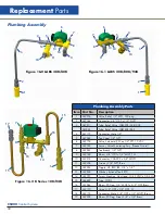
Page 42: ...y 1 4 FPT 12 VDC 7 367789 Sensor Valve Monitoring Assy Freeze Guard 8 367267 Tee Branch 1 4 NPT 9 367169 Elbow 3 8 ODT x 1 4 MNPT SS 10 367318 Connector CGA295 x 3 8 MNPT 11 367326 Strainer 3 8 NPT Brass 12 367254 Nipple HX RED BR 3 8 x 1 4 13 367246 Washer Extrenal Tooth 10 14 367723 Screw Machine Hex Head 10 32 UNC x 0 44 LG 15 366889 Tube Fill Kit 16 367264 Elbow 90 Deg 1 4 MNPT x 3 9 ODT Brass...

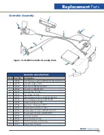
Page 43: ...91 Valve Freezegaurd Harness LABS20K 38K 40K 367792 Valve Freezegaurd Harness LABS80K 94K 7 367782 Harness Assembly CS LABS 8 367788 Level Sensor 8 Thermistor CS200 9 367785 Thermocouple Assembly CS LABS 10 367786 Thermocouple Wire Short LABS20K 38K 40K 367787 Thermocouple Wire Short LABS80K 94K 11 367795 Lid Switch Assembly 12 367796 Lid Switch Extension Wire 13 367823 12 VDC Transformer EL V No ...

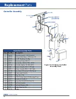
Page 44: ...er No Plug 4 367824 Transformer Cover LABS CS 5 367913 Junction Box With No T Plate CS200 6 367908 Controller Module 10K 24K CS200 7 367911 Harness Assembly 10K CS 74 Cable 367912 Harness Assembly 24K CS 104 Cable 8 367788 Level Sensor 8 Thermistor CS200 Control 9 366891 Thermocouple Assembly 10 367859 Plug Sensor Tube 11 367907 CS200 Display Module With Mounting Wings 12 367509 Display Module Bez...

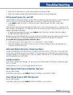
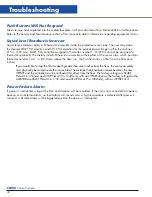
Page 45: ... is determined by thermistors located in the sensor tube If the sensor tube is blocked or iced at the top the liquid level in the sensor tube may not rise and fall at the same rate as the liquid level in the freezing chamber Make sure the sensor tube is not obstructed 3 The pool of LN2 can become turbulent during a fill Bubbling and splashing can be amplified by the rack arrangement The deeper the...

Page 46: ...akes for Liquid LN2 to reach the Freezer through the usual piping conditions Pipe Temperature at start fill Liquid should be entering the chamber within 4 minutes under normal usual line temperature conditions 3 Confirm that the solenoid valve is open when a fill is called for If no flow is detected the solenoid valve is not getting the signal to open or it is opening and there is a blockage in th...

Page 47: ...rd corrosion could be attributable to moisture invasion on the controller circuit board To troubleshoot proper operation of the fill valve 1 Confirm the pressure of the supply vessel is less than 22 psi 1 4 bar 138 kPa 2 Watch the interface panel on the controller to verify if the Start and Stop Fill cycles are repeating You should see and hear each cycle Solenoid Makes Excessive Humming Noise Dur...

Page 48: ...ch positions thermistor number 1 at 1 in 25 4 mm above the floor i e the first thermistor is offset from the floor zero inches If you would like to stop the fill at a depth greater than seven inches from the floor the sensor assembly must physically be raised inside the sensor tube The distance that it has been raised becomes the new OFFSET and the controller must be notified of this offset from t...

Page 49: ...______________________________________ LN2 Supply_______________ ltr______________ psi Supply Alarm_______On________ Off Note Ice Build up______a little______a lot Remote Alarm_______ On________Off Note Gasket condition______ Seals______ Leaks Audible Alarm______ On________Off Display Lights______On______ Off Temp control set point ___________ degrees Worthington Industries Technical Services Phon...

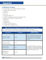
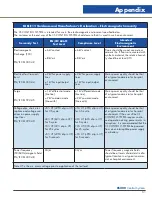
Page 50: ...fied below The customer or the end user of the CS CONTROL SYSTEM should assure that it is used in such an environment Emissions test Compliance Electromagnetic environment guidance RF Emissions CISPR 11 Radiated Conducted Group 1 The CS CONTROL SYSTEM uses RF energy only for its internal function Therefore its RF emissions are very low and are not likely to cause any interference in nearby electro...

Page 51: ...de line line 2kV common mode line earth 1kV differential mode line line 2kV common mode line earth Mains power quality should be that of a typical commercial or hospital environment Voltage dips short inter ruptions and voltage vari ations on power supply input lines EN IEC 61000 4 11 5 UT 95 dip in UT for 0 5 cycle 40 UT 60 dip in UT for 5 cycles 70 UT 30 dip in UT for 25 cycles 5 UT 95 dip in UT...

Page 52: ... in meters m Field strengths from fixed RF transmitters as determined by an electromagnetic site surveyA should be less than the compliance level in each frequency rangeB Interference may occur in the vicinity of equipment marked with the following symbol NOTE 1 At 80MHz and 800MHz the higher frequency range applies NOTE 2 These guidelines may not apply in all situations Electromagnetic propagatio...

Page 53: ...output power of transmitter in watts W Separation distance according to frequency of transmitter in meters m 150kHz to 80MHz d 1 2 P 80MHz to 800MHz d 1 2 P 800MHz to 2 5GHz d 2 3 P 0 01 12 12 23 0 1 38 38 73 1 0 1 2 1 2 2 3 10 3 8 3 8 7 3 100 12 12 23 For transmitters rated at a maximum output power not listed above the recommended separation distance d in meters m can be estimated using the equa...

Page 54: ... Low Voltage Directive and that the Standards and or technical specifications referenced below have been applied EN 60601 1 2006 A11 2001 Medical Electrical Equipment General Requirements for basic safety and essential performance IEC 61010 1 2001 Second Edition Safety requirements for electrical equipment for measurement control and laboratory use Part 1 General requirements IEC 60601 1 2 2007 Ed...

Page 55: ...y systems This warranty is void if the product is in any way altered or repaired by others Worthington Industries and or its suppliers shall not be liable under this warranty or otherwise for defects caused by negligence abuse or misuse of this product corrosion fire or the effects of normal wear The remedies set forth herein are exclusive Worthington Industries shall not be liable for any indirec...

Page 56: ...d CS200 Controller Operation Manual P N 372409 01 17 CONTACT US US Toll Free 844 273 7517 Global 43 7485 606 286 1 614 438 7968 Sales Support Order Placement customerservice worthingtonindustries com Technical Services techservices worthingtonindustries com ...

Reviews: