2-in-1 Grass Trimmer/Edger
En
12
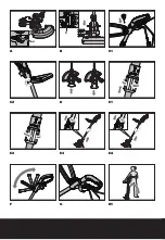
Adjust the trimmer head angle to be the
lowest horizontal setting (See
“Adjust
the trimmer head angle to the lowest
horizontal setting”
, Fig H1). Then position
the Edger Wheel (8) on the ground for edge
mode (See Fig. I). There are two white lines,
located on each end of the Safety Guard (4),
that show the cutting plane of the trimmer
line. Align these marks with the edge of your
lawn.
While edging, allow the tip of the line to make
contact. Do not force the line. The wheel helps
to prevent the unit from touching the ground.
Take extra caution while edging as objects
can be thrown from the trimmer line.
10. AuTOMATIC LINE FEED SySTEM
When initially switching on the trimmer, a
small length of line is fed out.
A ‘clattering’ noise will be heard for a short
time. This is normal and is caused by the line
being cut by the line cutter. Once the line is
cut to the correct length, the ‘clattering’ noise
will stop and the trimmer motor will run at
full speed.
To feed more line, stop the trimmer
completely, then restart, allowing the motor
to reach full speed. Repeat this until you hear
the ‘clattering’ noise of the line cutting. (Do
not repeat this procedure more than 6 times)
11. MANuALLy FEEDING THE LINE (See
Fig. J)
Press and release the Line Feed Button (15)
(See Fig. J) whilst gently pulling out on one of
the lines until it has reached the line cutter.
When the required amount of line is fed out,
gently pull on the second line (there is no
need to press the Line Feed Button again). If
the line extends past the line cutter, too much
line has been fed out.
If too much line is fed out, remove the spool
cap and click the spool counter-clockwise until
the line is at the desired length.
12. REMOVING THE CAP
Press and hold in the two Cap Release
Latches (11) (See Fig. K).
Pull the Cutting Head Cover (10) away from
the Cutting Head (13). Keep the Cutting Head
Cover and the inside of the Cutting Head
clean from debris. To replace the Cutting
Head Cover, press it firmly onto the spool
holder. Ensure that it is correctly connected
by trying to remove it without depressing the
two Cap Release Latches.
13. CHANGING THE LINE SPOOL:
First take off the Cutting Head Cover (10) and
remove the old Spool (12). Place the new
Spool onto the Cutting Head (13). Feed one
line through the Eyelet (14), and then repeat
for the second line. Reattach the Cutting
Head Cover.
wARNING!
Your Trimmer is designed
to only use line with a maximum
diameter of 1.65mm. Only use nylon line.
IMPORTANT
- Always wind the line onto the
upper section of the spool first.
14. TO MANuALLy wIND LINE
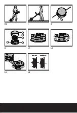
Take approximately 5m of line and insert
15mm of line into one of the holes in the
upper section of the Spool (12) (See Fig L1).
Wind the line in the direction of the arrows
on the top of the Spool. Repeat process with
separate piece of line on lower section of
Spool (See Fig. L2 & L3).
Leave approximately 100mm of line unwound
and place it into the cleat. Repeat on the
lower section of the Spool.
Care should be taken to ensure that the line
is neatly coiled on the Spool (See Fig. L4).
Failure to do so will impair the efficiency of
the automatic line feed.
Then fit the Spool as described above in
“Changing the Line Spool”
.
mainTEnancE
After use, disconnect the machine from
the electrical outlet and check for damage.
Your trimmer requires no additional
lubrication or maintenance. There are no user
serviceable parts in your trimmer. Electric
powered trimmers should only be repaired
by an authorized repairer. Use only WORX
replacement parts and accessories.
Never use water or chemical cleaners to clean
your trimmer. Wipe clean with a dry cloth.
Always store your trimmer in a dry place
out of the reach of children. Keep the motor
ventilation slots clean. If you see some sparks
flashing in the ventilation slots, this is normal
and will not damage your trimmer.
Summary of Contents for WG117E
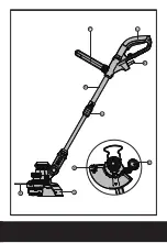
Page 3: ...3 2 4 5 7 1 6 9 8...
Page 4: ...b a A B C1 C2 D E1 E2 E3 E4 F G H1...
Page 5: ...14 RIGHT WRONG 10 11 12 13 14 F G H1 H2 I J L2 K L1 L3 L4...
Page 104: ...2 1 GR 104 104 1 2 3 4 5 6 7 8 9 10 K 11 K 12 K 13 K 14 K 15 L...
Page 106: ...2 1 GR 106 106 10 C 1 1 1 1...
Page 107: ...107 2 1 GR 107 a b c d e f g h i j k l...
Page 108: ...2 1 GR 108 108 2002 96 CE RCD 30mA...
Page 109: ...109 2 1 GR 109 1 A 4 a 2 B b 3 C1 C2 1 2 3 C1 4 C2 1 65mm 1 D 5 D...
Page 111: ...111 2 1 GR 111 4 6 11 J 15 J 12 11 K 10 13 13 10 12 13 14 1 65 mm 14 5 15 mm L2 L3 WORX...
Page 113: ...113 113 2 1 RU 1 2 3 4 5 6 7 8 9 10 K 11 K 12 K 13 K 14 K 15 L...
Page 115: ...115 115 2 1 RU 10 C 1 1 1 1...
Page 116: ...116 2 1 RU 116 1 2 3 4 5 6 7 8 9 10 11 12 a b c d...
Page 117: ...117 117 2 1 RU 30 Tenez vous bonne distance Ne pas exposer la pluie ou l eau 2002 96 CE...
Page 118: ...118 2 1 RU 118 1 A 4 2 B b 3 C1 C2 1 2 3 C1 4 C2 1 65 1 D 5 D...
Page 120: ...120 2 1 RU 120 4 6 11 J 15 J 12 11 K 10 13 13 10 12 13 14 1 65 14 5 15 L2 L3 100 WORX...
Page 122: ......
Page 123: ......
Page 124: ...Copyright 2013 Positec All Rights Reserved 2GGT12APK11001A0...


