background image

Cordless Grass Trimmer                      ENG

7

6

7

6

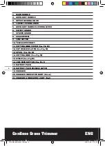
1.  MAIN HANDLE
2.  AUXILIARY HANDLE
3.  UPPER LOCKING KNOB
4.  LOWER LOCKING KNOB 
5.  AUXILIARY HANDLE LOCKING LEVER
6.  SAFETY GUARD
7.  SPACER GUARD
8.  EDGER WHEEL
9.  LINE CUTTER
10. TELESCOPIC SHAFT
11. CUTTING HEAD COVER (See Fig M)
12. CAP RELEASE LATCH (See Fig M)
13. SPOOL (See Fig M)
14. CUTTING HEAD (See Fig M)
15. EYELET (See Fig M)
16. LINE FEED BUTTON (See Fig L)
17. BATTERY PACK
18. BATTERY PACK RELEASE LATCH
19. CHARGER
20. CHARGED INDICATOR LIGHT (Green)
21. CHARGING INDICATOR LIGHT (Red)

CRA-WG150E-M-061102.indd   6

2007-3-28   17:11:01

Summary of Contents for WG150E

Page 1: ...WG150E CRA WG150E M 061102 indd 1 2007 3 28 17 10 50...

Page 2: ...CRA WG150E M 061102 indd 2 2007 3 28 17 10 50...

Page 3: ...CRA WG150E M 061102 indd 3 2007 3 28 17 10 50...

Page 4: ...A B C CRA WG150E M 061102 indd 4 2007 3 28 17 10 52...

Page 5: ...D E F G H I J K L M CRA WG150E M 061102 indd 5 2007 3 28 17 10 57...

Page 6: ...EDGER WHEEL 9 LINE CUTTER 10 TELESCOPIC SHAFT 11 CUTTING HEAD COVER See Fig M 12 CAP RELEASE LATCH See Fig M 13 SPOOL See Fig M 14 CUTTING HEAD See Fig M 15 EYELET See Fig M 16 LINE FEED BUTTON See Fi...

Page 7: ...ver 85dB A Typical weighted vibration 4 0m s2 ACCESSORIES Battery 18V 1 7Ah Ni Cd 1pc 1 hour charger Voltage 220V 240V 50Hz 60Hz 1pc We recommend that you buy all your accessories from the store where...

Page 8: ...nd use common sense when operating a power tool Do not use a power tool while you are tired or under the in uence of drugs alcohol or medication A moment of inattention while operating power tools may...

Page 9: ...ther metal objects like paper clips coins keys nails screws or other small metal objects that can make a connection from one terminal to another Shorting the battery terminals together may cause burns...

Page 10: ...ING YOUR BATTERY PACK WARNING The charger and battery pack are speci cally designed to work together so do not attempt to use any other devices Never insert or allow metallic objects into your charger...

Page 11: ...rimmer has been switched off wait until it has stopped then lay down the tool 6 ADJUSTMENT OF THE TELESCOPIC SHAFT SEE G Unscrew the lower locking knob 4 in the direc tion indicated to unlock Adjust t...

Page 12: ...art allowing the motor to reach full speed Repeat above 4 until you hear the lines hitting against the line cutter Do not repeat this procedure more than 6 times TO MANUALLY FEED THE LINE SEE FIG L If...

Page 13: ...ected to the terminal which is marked with L WARNING Never connect live or neutral wires to the earth terminal of the plug Only t an approved 13Amp BS1363 A plug and the correct rated fuse NOTE If a m...

Page 14: ...lity Directive 89 336 EEC amended by 93 68 EEC Noise Emission in the Environment by Equipment for Use Outdoors Directive 2000 14 EC Conformity Assessment Procedure as per Annex VI Measured Sound Power...

Page 15: ...15 CRA WG150E M 061102 indd 15 2007 3 28 17 11 08...

Page 16: ...CRA WG150E M 061102 indd 16 2007 3 28 17 11 08...

Reviews: