background image

10

3 in 1 Grass Trimmer/Edger

EN

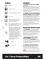
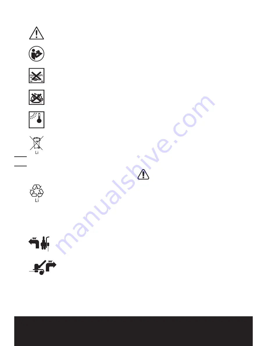
Warning

Read the manual 

Do not expose to rain or water

Do not burn

Always charge the battery pack 
between temperatures 40°F 
(4.5°C)-105°F (40.5.°C).

Do not dispose of batteries, return 
exhausted batteries to your local 
collection or recycling point

BATTERY PACK REMOVAL AND 
PREPARATION FOR RECYCLING
 To preserve natural resources, 
please recycle or dispose of 
batteries properly. This product 
contains lithium-ion batteries. 
Local, state or federal laws may 
prohibit disposal of lithium-
ion batteries in ordinary trash. 
Consult your local waste authority 
for information regarding 
available recycling and/or 
disposal options.

          Edging

           Trimming

40-105ºF

sYMBoLs

AssEMBLY

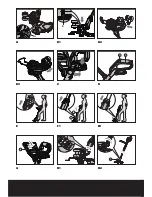
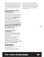
1. aSSEmBly oF THE SaFETy GuaRd 

(See Fig. a) 

Remove a screw from the Guard; attach the 
Safety Guard to the trimmer head. Align the 
Guard so it slides into the slots located on the 
trimmer head. Turn the tool over and secure 
the Safety Guard onto the trimmer head with 
the screw (a) provided.

2. aSSEmBly oF THE EdGER/TRimmiNG 

SuPPoRT  wHEElS (See Fig. B1, B2, B3)

With the tool right side up, slide the Edger/
Trimming Support Wheels (12) assembly onto 
the metal plate located on the side of the 
Cutting Head (See Fig. B1) or underneath the 
Safety Guard (5) (See Fig. B2, B3). Make sure 
the grooves of the Edger/Trimming Support  
Wheels assembly locks onto the metal plate, 
you will hear it click into place. 
To remove the  wheels assembly, press the 
release button (b) on the wheel and pull the  
wheels outside. 

oPErATIoN INsTrUCTIoNs

waRNiNG! 

The charger and Battery 

Pack are specially designed to work 

together so do not attempt to use any other 
devices. Never insert or allow foreign metallic 
objects into your charger or Battery Pack 
connections because of electrical failure and 
other hazards that will occur.

1. BEFoRE uSiNG youR CoRdlESS 

GRaSS TRimmER

Your Battery Pack is 

uNCHaRGEd

 and it 

must be fully charged once before it is used.
The battery charger supplied is matched to the 
Li-Ion battery for use with this tool. Do not use 
another battery charger.

2. CHaRGiNG youR BaTTERy PaCk

The Li-Ion battery is protected against deep 
discharging. When the battery is empty, 
the trimmer will switch off by means of a 
protective circuit: The trimmer head will stop 
rotating.

NoTE:

 In a warm environment or after heavy 

use, the Battery Pack may become too hot to 

Summary of Contents for WG160

Page 1: ...WG160 WG160 1WG175 HElPliNE NumBER 1 866 354 woRx 9679 HElPliNE NumBER P06 P15 P25 3 in 1 Grass Trimmer Edger Coupe gazon Taille bordure 3 en 1 3 en 1 Cortadora de cesped Ribeteadora EN F ES...

Page 2: ......

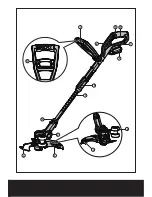
Page 3: ...4 6 7 9 10 2 1 5 8 3 14 15 13 12 11...

Page 4: ...b 9 a 10 14 11 15 16 A B1 B2 B3 C D E F1 F2 G H1 H2...

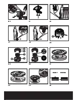
Page 5: ...22 18 19 20 21 17 RIGHT WRONG H3 I1 I2 J1 J2 K1 K2 K3 L1 L2 L3 L4...

Page 6: ...ton 10 On Off Switch 11 Auxiliary Handle Locking Lever 12 Edger Trimming Support Wheels 13 Line Cutter 14 Lower Shaft Coupling 15 Upper Shaft 16 Motor Housing of Trimmer Head 17 Line Feed Button See F...

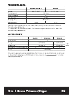
Page 7: ...al voltage is 18 volts Voltage measured without workload Initial battery voltage reaches maximum of 32 volts Nominal voltage is 28 8 volts Accessories WG160 WG160 1 WG175 Safety Guard 1 Charger 1 WA37...

Page 8: ...any job except that for which it is intended 7 Avoid Unintentional Starting Don t carry plugged in appliance with finger on switch Be sure switch is off when plugging in 8 Don t Force Appliance It wi...

Page 9: ...lode Check with local codes for possible special disposal instructions 3 Do not open or mutilate the battery ies Released electrolyte is corrosive and may cause damage to the eyes or skin It may be to...

Page 10: ...ight side up slide the Edger Trimming Support Wheels 12 assembly onto the metal plate located on the side of the Cutting Head See Fig B1 or underneath the Safety Guard 5 See Fig B2 B3 Make sure the gr...

Page 11: ...ur Auxiliary Handle has been locked 8 ADJUSTMENT OF THE TRIMMER HEAD ANGLE TO THE SHAFT See Fig H1 H2 H3 Warning Make Sure the Safety Switch is Locked Off to Prevent Accidental Starting To adjust the...

Page 12: ...trimmer head angle to be in the lowest horizontal setting Finally lock the Pivot Head Locking Knob and position the wheel on the ground for the edging mode While edging keep the Flower Guard Edger Gui...

Page 13: ...e Spool facing inward or down When installed into the Spool Holder the smooth side of the Spool should be visible Release line from cleat on the Spool Refit the Spool Cap Cover To Manually Wind line S...

Page 14: ...for long period or only charged for short term Grass is too high Battery defective Fully charge battery also see the content in charger manual Cut in stages Replace the battery Machine does not cut Li...

Page 15: ...gagement de poign e 12 Roue de support coupe bordures lagage 13 Coupeur De Cordon De Coupe 14 Bo tier inf rieur d engrenage 15 Poign e sup rieure 16 Habitacle du moteur de la t te du coupe herbe 17 Bo...

Page 16: ...s La tension nominale est de 18 V Tension mesur e hors fonctionnement La tension initiale de la batterie atteint le maximum de 32 volts La tension nominale est de 28 8 V ACCESSOIRES WG160 WG160 1 WG17...

Page 17: ...reuse 6 Utilisez le bon appareil N utilisez pas l appareil pour tout autre travail que pour celui auquel il est destin 7 vitez les d marrages non intentionnels Ne transportez pas les appareils alors q...

Page 18: ...iles de type ou grosseurs suivants WA 3525 WG160 WG160 1 WA3537 WG175 2 Ne disposez pas des piles en les jetant dans feu La cellule peut exploser V rifiez les r glementations locales pour de possibles...

Page 19: ...la vis fournie cet effet localis l int rieure de la garde 2 ASSEMBLAGE DE LA ROUE DE SUPPORT DE COUPE BORDURES LAGAGE Voir Fig B1 B2 B3 Avec l outil l endroit faites glisser l assemblage de la roue d...

Page 20: ...n 6 ROTATION DE LA POIGN E PRINCIPALE Voir Fig F1 F2 Retenez d abord du pied la partie inf rieure et tirez le manche t lescopique 15 vers le haut Tournez ensuite le manche t lescopique 90 degr s dans...

Page 21: ...it est situ e une plaque m tallique auquel les roues de support du coupe bordures lagueur s attacheront Faites glisser les roues de support verticalement sur la plaque m tallique jusqu ce qu elles s e...

Page 22: ...de la t te de coupe et enlevez tous les d bris Pour replacer le couvercle de la bobine appuyez fermement sur le support de bobine Assurez vous qu il est correctement connect en essayant de l enlever s...

Page 23: ...de soutien la client le contactez le centre d assistance aux consommateurs WORX au 1 866 354 WORX AVERTISSEMENT teindre l appareil et retirer la batterie avant toute tentative de r paration Probl me C...

Page 24: ...ntacts batterie par ex en mettant et en retirant la batterie plusieurs reprises ou remplacer la batterie Remplacer la batterie Indicateur de charge de la batterie ne s allumant pas La prise du chargeu...

Page 25: ...terruptor de encendido apagado 11 Liberador del mango 12 Rueda de apoyo de recorte rebordeadora 13 Cuchilla del hilo 14 Acoplamiento del eje inferio 15 Mango Superior 16 Tapa del motor del cabezal de...

Page 26: ...El voltaje nominal es 18 V Voltaje medido sin carga de trabajo El voltaje inicial de la bater a alcanza un m ximo de 32 V El voltaje nominal es 28 8 V Accesorios WG160 WG160 1 WG175 Guarda protectora...

Page 27: ...i n adecuada para contener el cabello largo 5 Utilice gafas de seguridad Emplee siempre m scara para la cara o m scara anti polvo en operaciones donde se emite mucho polvo 6 Utilice la herramienta cor...

Page 28: ...smontable o independiente debe contener las siguientes instrucciones u otras equivalentes 1 Use nicamente el siguiente tipo y tama o de bater as WA3525 WG160 WG160 1 WA3537 WG175 2 No tire las bater a...

Page 29: ...juste la guarda de seguridad con el tornillo suministrado localizado en el interior de la guarda 2 ARMADO DE LA RUEDA DE APOYO DE RECORTE REBORDEADORA Ver Fig B1 B2 B3 Con el lado derecho de la herram...

Page 30: ...ia arriba del mango telesc pico 15 A continuaci n gire el mango telesc pico 90 grados hacia la derecha Ver Fig F1 y su ltelo El mango quedar bloqueado autom ticamente en su posici n Ver Fig F2 7 AJUST...

Page 31: ...de apoyo de forma vertical hacia la placa de metal hasta que queden aseguradas en su posici n Ver Fig B2 Las ruedas deber n proporcionar un apoyo al realizar recortes en una direcci n de lado a lado h...

Page 32: ...er Fig K3 Apague la cortadora de c sped y extraiga la bater a Extraiga la cubierta de la tapa de la bobina Para su comodidad se recomienda adquirir bobinas de reemplazo con la l nea de corte preinstal...

Page 33: ...contacto con un agente de servicio t cnico P ngase en contacto con un agente de servicio t cnico La podadora funciona de forma intermitente Motor da ado Bater a no cargada totalmente Interruptor de e...

Page 34: ...er a El indicador de carga de la bater a 18 no se enciende Cargador de bater as no enchufado de forma correcta Tomacorriente cable de alimentaci n o cargador de bater as da ado Inserte el enchufe por...

Page 35: ......

Page 36: ...Designed in Italy Made in China Con u en Italie Fabriqu en Chine Dise ado en Italia Fabricado en China Copyright 2013 Positec All Rights Reserved...

Reviews: