11
10
Electric Lawn Mower
EN
11
10
INTENDED USE
This product is intended for domestic lawn
mowing.
ASSEMBLy
IMPORTANT!
Before you assemble
the lawn mower, check the accessories
according above information, make sure the
accessories are completed.
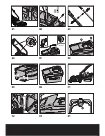
1. FITTING ThE hANDLE (See Fig. A1,
A2, A3, A4)
1) Remove the screws (X2) on the both side of
deck (See Fig. A1).
2) Insert the lower handle (9) into the holes
provided.
3) Secure with the screws provided (See Fig.
A2).
4) Attach the upper handle (8) with the bolts
and lock cam lever (3) to the lower handle
(9) (See Fig. A3).
5) Tightening the two Lock cam levers. Check
that the handle is FULLY secured.
The cam lever pressure can be adjusted by
adjusting the lock cam lever (3) clockwise/
counter-clockwise. DO NOT OVER TIGHTEN.
NOTE:
Ensure the bolts are fully inserted
through the handles before fitting the handle
knobs.
6) Attach the cable clips (2) provided, to the
upper and lower handle. Insert the cable
into the clips ensuring there is enough
cable slack (See Fig. A4).
2. GRASS COLLECTION BAG ASSEMBLy
Connect the grass box handle to the box top
as shown in Fig B1-B4.
Step 1. Press the front of the handle briefly
(See Fig. B2).
Step 2. Then push it forward (See Fig. B2).
Step 3. Push down the back of the handle
(See Fig. B2).
Step 4. Clip the plastic clips over the metal
frame (See Fig. B3).
WARNING: Don’t fit the handle in
reversed direction. Fit the handle as
shown in Fig B1.
3. GRASS COLLECTION BAG FITTING
(See Fig. C1, C2, C3)
1) Turn the mower off, wait until blade stops.
2) Raise the safety flap (10) and hold it up.
3) Pick up the grass bag by the handle, and
position grass bag on the lower hooks (a)
on the mower deck (See Fig. C2).
4) Release the safety guard to lock the grass
bag into position. Ensure the grass bag is
installed securely (See Fig. C3).
NOTE:
Depress the grass bag slightly to
ensure that it is completely installed.
4. REMOVING/EMPTyING
Hold the grass bag, lift the safety flap (10) and
hold up. Remove grass bag (5).
WARNING!
Always check the safety flap
can close the discharge outlet tightly
before using. Never lift the safety flap (10)
when the lawn mower is being used without
fitted grass bag.
OPERATION
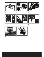
1. STARTING AND STOPPING (See Fig.
D1, D2)
STARTING
Connect the plug to the mains and switch ON.
The switch box is provided with a lock-
off button to prevent accidental starting.
With one hand press and hold the safety
button (D1), with the other hand squeeze the
switch lever (D2) towards the handle, and
release the safety lock-off button. The machine
is now started, wait until the product is at full
speed before cutting the grass. Then use both
your hands to hold the switch lever on both
sides to keep it running.
STOPPING
Release the switch lever.
2. hOW TO MOW
For cutting convenience, it may be best to start
mowing at a point close to the power supply
and to work your way away from the supply.
Mow the lawn at a right angle from the power
supply and place the power cable to side
which has already been cut.
NOTE: The motor is protected by a safety
cut out which is activated when the
Summary of Contents for wg706e
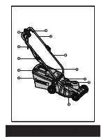
Page 3: ...1 2 3 4 5 6 7 8 9 10 11 12...
Page 4: ...Front Part Back Part a 1 a 1 2 3 2 1 A1 A2 A3 A4 B1 B2 B3 B4 C1 C2 C3 D1...
Page 5: ...1 2 a b 14 13 1 2 1 2 C2 C3 D1 D2 E F I1 G H I2 J...
Page 99: ...99 99 GR 1 2 3 4 5 6 7 8 9 10 11 12 13 I1 14 I1...
Page 101: ...101 101 GR 1 2 3 4 1 2 3 4 1 2 3 4 5 6 7 8 9 10 11 12 13...
Page 102: ...102 GR 102 14 1 2 3 4 RCD 30mA...
Page 104: ...104 GR 104 B2 4 B3 B1 3 C1 C2 C3 1 2 3 a C2 4 C3 4 10 5 10 1 D1 D2 D1 D2 2 3 E...
Page 105: ...105 105 GR 4 F 5 G 1 2 20mm TURBO TURBO 6 H 3 20mm 60mm I1 I2 14 13 I1 50 2...
Page 107: ...107 107 RU 1 2 3 4 5 6 7 8 9 10 11 12 13 I1 14 I1...
Page 109: ...109 RU 1 2 3 4 1 2 3 4 1 2 3 4 5 6 7 8 9...
Page 110: ...110 RU 10 11 12 13 14 1 2 3 4 30...
Page 111: ...111 RU 1 A1 A2 A3 A4 1 X 2 A1 2 9 3 A2 4 8 3 9 A3 5 3 6 2 P A4 2 B1 B4 1 2002 96 CE...
Page 112: ...112 RU P B2 2 P B2 3 P B2 4 P C3 B1 3 C1 C2 C3 1 2 3 a C2 4 y C3 4 10 5 10 1 D1 D2 D1 D2 2 3 E...
Page 113: ...113 RU a b 4 F 5 G 1 2 20 N 6 H 3 20 60 I1 I2...
Page 114: ...114 RU 14 13 I1 50 2 J 11 2002 96 CE...
Page 116: ...Copyright 2013 Positec All Rights Reserved 2GLM11APK11001A2...

