background image

13

12

13

12

Cordless Lawn mower   


EN

1.  FITTING ThE haNDLE (See b1~b5)

1)  Remove the screws (X 2) on the both side 

of deck. (Fig B1)

2)  Insert the lower handle (9) into the holes on 

the deck provided.(Fig B2)

3)  Secure with the screws provided.(Fig B2)
4)  Attach the upper handle (7) with the bolts 

and lock cam lever (8) to the lower handle 
(9). (Fig B3)

5)  Tightening the two Lock cam levers. Check 

that the handle is FULLY secured.

  The cam lever pressure can be adjusted by 

adjusting the lock cam lever (8) clockwise/
counter-clockwise. DO NOT OVER TIGHTEN.
(Fig. B4)


NOTE:

 Ensure the bolts are fully inserted 

through the handles before fitting the 
handle knobs.

6)  Attach the cable clips (2) provided, to the 

upper and lower handle. Insert the cable 
into the clips ensuring there is enough 
cable slack. (Fig B5)

2. GRaSS COLLECTION baG aSSEmbLy

Connect the grass box handle to the box top 
as shown in F ig C1-C4.
Step 1   press the front of the handle briefly.  

(Fig C2)

Step 2   Then push it forward. (Fig C2)
Step 3   push down the back of the handle. 

(Fig C2) 

Step 4   Finally, clip the plastic clips over the 

metal frame. (Fig C3) 

waRNING: Don’t fit the handle in 

reversed direction. Fit the handle as 

shown in Fig C1.

3. GRaSS COLLECTION baG FITTING 

(See D1, D2, D3)

1)  Turn the mower off, wait until blade stops 

and remove safety key (6).

2)  Raise the safety flap (10) and hold it up, 

ensure that the mulching insert has been 
removed.

3)  pick up the grass bag by the handle, and 

position grass bag on the lower hooks (a) 
on the mower deck (Fig. D2).

4)  Release the safety guard to lock the grass 

bag into position. Ensure the grass bag is 
installed securely (Fig. D3).

NOTE:

 Depress the grass bag slightly to 

ensure that it is completely installed.

4. REmOVING/EmPTyING

Hold the grass bag, lift the safety flap (10) and 
hold up. Remove grass bag (4). 

waRNING!

 Always check the safety flap 

can close the discharge outlet tightly 

before using. Never lift the safety flap (10) 
when the lawn mower is being used without 
fitted grass bag.

5. haNDLE aDJUSTmENT (See E)

The upper handle can be adjusted to 3 
different height positions. Release the locking 
cam lever, set the upper handle to one of the 
three height positions, and make sure to insert 
the pin into the hole.  Then reset the locking 
cam lever.

NOTE:

 Always check that the upper handle is 

fixed firmly.

6. FITTING/REmOVING baTTERy (See F1, 

F2)

REmOVING baTTERy

pull out the battery with the battery handle 
directly. (See F1)

NOTE:

 Be careful not to drop the battery onto 

your foot or on the ground when removing it. 

FITTING baTTERy

put the battery into the battery container; make 
sure the battery is fitted correctly. (See F2)

OPERATION

1. STaRTING aND STOPPING (See G1, G2)

waRNING! 

The blade continues 

to rotate for a few seconds after the 

machine is switched off. Allow the motor/blade 
to stop rotating before switching “on” again. 
Do not rapidly switch off and on.

STaRTING

1)  Insert safety key into the housing of the 

switch box. 

2)  Slide the key to the right and hold in 

position.

3)  pull the lever bar towards the handle and 

the mower will start.

4)  Release the safety key.

Summary of Contents for WG785E

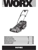
Page 1: ...P08 P19 P31 P42 P53 P64 WG785E Cordless lawn mower EN Schnurloser Rasenm her D Tondeuse gazon sans fil F Falciatrice per prato senza fili I Cortac sped sin cables ES Snoerloze graasmaaier NL...

Page 2: ...ions EN bersetzung der Originalanleitung D Traduction des instructions initiales F Traduzione delle istruzioni originali I Traducci n de las instrucciones originales ES Vertaling van de oorspronkelijk...

Page 3: ......

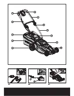
Page 4: ...13 11 A2 A1 B1 1 6 7 8 9 10 11 12 2 3 4 5...

Page 5: ...a Front Part Back Part 1 2 3 1 2 B4 B5 B3 C1 B2 C2 C3 C4 D1 D2 D3 E...

Page 6: ...14 1 PRESS 1 2 N 1 N 2 N 3 a b 1 2 O 1 O 2 O 3 F2 G1 F1 H I G2 K L J N O M...

Page 7: ...15 16 P2 Q P1...

Page 8: ...llection bag 5 Work mode dial 6 Safety key 7 Upper handle 8 Lock cam lever 9 Lower handle 10 Safety flap 11 Battery pack 12 Motor cover 13 Charger see A2 14 Mulch insert see H 15 Blade bolt see P1 16...

Page 9: ...LpA 80dB A TURBO mode KpA 3dB A LpA 70dB A QUIET mode KpA 3dB A A weighted sound power LwA 93dB A Wear ear protection when sound pressure is over 80dB A Typical weighted vibration 4 0m s2 K 1 5m s2 AC...

Page 10: ...to see that the blades blade bolts and cutter assembly are not worn or damaged Replace worn or damaged blades and bolts in sets to preserve balance d On multi bladed machines take care as rotating one...

Page 11: ...his machine Warning Keep bystanders away Blade continues to rotate after the machine is switched off Wait until all machine components have completely stopped before touching them Beware of sharp blad...

Page 12: ...t you have power and the battery is being charged 5 The red light will turn off and the green light will come on when charging is complete approximately 10 12 hours to charge a fully discharged batter...

Page 13: ...osition grass bag on the lower hooks a on the mower deck Fig D2 4 Release the safety guard to lock the grass bag into position Ensure the grass bag is installed securely Fig D3 NOTE Depress the grass...

Page 14: ...a highly charged condition When two lights are illuminated the battery is in a moderately charged condition When only one green light is illuminated the battery charge is depleted Before using your ne...

Page 15: ...lching performance 1 Avoid mowing when the grass is wet from rain or dew Wet grass may form clumps which interfere with the mulching action and reduce runtime The best time to mow grass is in the late...

Page 16: ...lade balancing 7 Replace blade on mower and tighten securely Refer to instructions below BLADE BALANCING See O Check balance of blade by placing center hole in blade O 1 over a nail or screwdriver sha...

Page 17: ...follows The wire which is colored blue must be connected to the terminal which is marked with N The wire which is colored brown must be connected to the terminal which is marked with L Warning Never...

Page 18: ...nded by 2005 88 EC Conformity assessment procedure as per Annex VI Measured Sound Power Level 80 dB A TURBO mode 70 dB A QUIET mode Declared Guaranteed Sound Power Level 93dB A The notified body invol...

Page 19: ...smodusw hler 6 Sicherheitsschl ssel 7 Griffoberteil 8 Haltenocken Hebel 9 Griffunterteil 10 Sicherheitsklappe 11 Batteriepack 12 Motorabdeckung 13 Aufladeger t Siehe A2 14 Mulch Einsatz Siehe H 15 Bla...

Page 20: ...Turbomodus KpA 3dB A LpA 70dB A Leiser Modus KpA 3dB A Gewichtete Schallleistung LwA 93dB A Tragen Sie bei einem Schalldruck ber einen Geh rschutz 80dB A Typischer gewichteter Vibrationswert 4 0m s2 K...

Page 21: ...ungen anderer Personen oder deren Eigentum die Verantwortung tr gt VORBEREITUNG a Tragen Sie beim M hen stets festes Schuhwerk und eine lange Hose Den Rasenm her nicht barfu oder mit offenen Sandalen...

Page 22: ...tark vibiriert WARTUNG UND AUFBEWAHRUNG a Den Festsitz aller Schrauben Muttern und Bolzen sicherstellen um zu gew hrleisten dass sich der Rasenm her in einem betriebssicheren Zustand befindet b Den Gr...

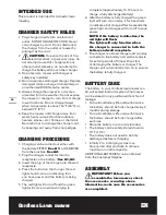
Page 23: ...l des Aufladeger tes von scharfen Kanten fern halten um es nicht zu besch digen AUFLADEPROZESS 1 Das Aufladen kann ausgef hrt werden wenn die Batterie in die Maschine EINGESETZT ist Siehe A1 oder aus...

Page 24: ...nweis Achten Sie darauf dass die Schrauben komplett durch das Griffst ck gef hrt wurden bevor Sie die Griffkn pfe anbringen Bringen Sie die Kabelklemmen 2 am oberen und unteren Griffst ck an F hren Si...

Page 25: ...chieben Sie den Schl ssel nach rechts dort halten 3 Ziehen Sie den Hebel an den Griff heran der M her l uft an 4 Lassen Sie den Sicherheitsschl ssel los AUSSCHALTEN Den Schaltb gel loslassen 2 EINBAU...

Page 26: ...zwischen 20mm und 70mm eingestellt werden Bewegen Sie zu diesem Zweck den Hebel f r das Einstellen der Schneideh he ausw rts und stellen ihn dann auf die gew nschte Position ein 7 Grasbeh lterf llsta...

Page 27: ...Sie die Schnitth he so einstellen dass Sie ungef hr ein Drittel der L nge der Halml nge abschneiden Idealerweise nicht mehr als 38mm auf einmal Wenn der Rasen berwuchert ist dann kann es notwendig sei...

Page 28: ...Klinge zum Stillstand gekommen ist und der Sicherheitsschl ssel entfernt wurde 2 Nehmen Sie die Klinge aus dem Rasenm her Lesen Sie die Anweisungen f r das Herausnehmen und Anbringen der Klinge 3 Sich...

Page 29: ...ch mit einem Holz oder Plastikst ck entfernen Den Rasenm her an einem trockenen Ort aufbewahren Keine anderen Gegenst nde auf die Maschine stellen Zum einfacheren Verstauen l sen Sie die Fixierhebel u...

Page 30: ...hinen Richtlinie 2000 14 EC ge ndert durch 2005 88 EC Konformit tsbewertungsverfahren nach Anhang VI Gemessene Schallleistung 80dB A Turbomodus 70dB A Leiser Modus Garantierte Schallleistung 93 dB A Z...

Page 31: ...Cadran du mode de fonctionnement 6 Cl de s ret 7 Poign e sup rieure 8 Levier de came de verrouillage 9 Poign e inf rieure 10 Volet de s curit 11 Batterie 12 Capot du moteur 13 Chargeur Voir A2 14 Inse...

Page 32: ...de turbo KpA 3dB A LpA 70dB A Mode SILENCIEUX KpA 3dB A Niveau de puissance acoustique LwA 93dB A Porter des protections auditives lorsque la pression sonore est sup rieure 80dB A Valeur de vibration...

Page 33: ...ns longs Ne pas utiliser a tondeuse pieds nus ou avec des chaussures ouvertes b Examinez compl tement la zone o le mat riel doit tre utilis et enlevez tous les objets susceptibles d tre projet s par l...

Page 34: ...p rateur d herbe c Par s curit remplacer toutes parties us es ou endommag es SYMBOLS Lire attentivement la notice et la conserver AVERTISSEMENT Tenez vous bonne distance La lame continue tourner apr s...

Page 35: ...MONT E Voir A1 ou ENLEV E de la machine Voir A2 2 Branchez le connecteur du chargeur dans la prise sur la batterie Voir A1 A2 3 Ins rez la fiche du chargeur dans la prise murale 4 Pressez le bouton d...

Page 36: ...e comme illustr dans les F ig C1 C4 tape 1 Pressez bri vement sur l avant de la poign e Fig C2 tape 2 Puis poussez la vers l arri re Fig C2 tape 3 Poussez vers le bas la partie arri re de la poign e F...

Page 37: ...tement ferm 3 RETIRER L INSERT DE PAILLAGE Voir H Pour retirer la hacheuse ins r e de fa on pouvoir collecter l herbe suivez les tapes list es ci dessous 1 Mettez la tondeuse hors fonction patientez j...

Page 38: ...RIS QUI POURRAIENT TRE PROJET S PAR LA LAME EN ROTATION 1 Tondez en travers des pentes jamais de haut en bas Faites extr mement en changeant de sens sur les pentes Ne tondez pas des pentes excessiveme...

Page 39: ...e peuvent exiger qu une zone soit paill e une deuxi me fois pour disperser enti rement l herbe dans toute la pelouse Si vous coupez une deuxi me fois il est recommand de couper perpendiculairement en...

Page 40: ...la condition qui se r alise le plus t t Suivez ces proc dures pour retirer et remplacer la lame Vous avez besoin de gants de jardin non fournis et d une cl fourche non fournie pour retirer la lame Ten...

Page 41: ...ure d valuation de la conformit conform ment Annex VI Niveau de pression acoustique ure as per Annex VI Niveau de pression acoustique l 80dB A Mode turbo 70dB A Mode SILENCIEUX Niveau d intensit acous...

Page 42: ...t operativa 6 Chiavetta di sicurezza 7 Impugnatura Superiore 8 Leva di bloccaggio a camma 9 Impugnatura Inferiore 10 Aletta di Sicurezza 11 Batteria 12 Carter Motore 13 Caricatore Vedere A2 14 Attacco...

Page 43: ...ne acustica ponderata A LpA 80 dB A Modalit Turbo KpA 3dB A LpA 70dB A Modalit Silenziosa KpA 3dB A Potenza acustica ponderata A LwA 93dB A Indossare protezione per le orecchie quando la pressione acu...

Page 44: ...area in cui si deve utilizzare l apparecchiatura e togliere tutti gli oggetti che potrebbero essere lanciati dall apparecchiatura c Prima dell uso verificare visivamente che le lame i rispettivi bullo...

Page 45: ...l dispositivo di raccolta erba c Per maggiore sicurezza sostituire le parti usurate o danneggiate LEGENDA SIMBOLI Leggere attentamente il manuale d istruzione ed assicurarsi di aver compreso completam...

Page 46: ...pu essere effettuata sia con la batteria MONTATA Vedere A1 o SMONTATA dall apparecchiatura Vedere A2 2 Collegare il caricatore alla presa presente sulla batteria Vedere A1 A2 3 Inserire la spina a de...

Page 47: ...i fermagli assicurandosi che abbia gioco sufficiente Fig B5 2 MONTAGGIO DEL SACCO RACCOLTA ERBA Collegare l impugnatura del raccoglitore sulla parte superiore del raccoglitore come mostrato nella Figu...

Page 48: ...ino all arresto complete della lama e togliere la chiavetta di sicurezza 2 Tenere sollevata la protezione 3 Far scorrere l attacco decespugliatore nell apertura di scarico fino a quando non viene bene...

Page 49: ...l area nella quale si deve utilizzare il tagliaerba e togliere pietre bastoni cavi ossi ed altra sporcizia che potrebbe essere lanciata dalla lama in rotazione 1 Tagliare l erba lungo la superficie d...

Page 50: ...e dopo ogni utilizzo 4 Alcuni tipi di prato o di condizioni del prato potrebbero rendere necessario un secondo passaggio del decespugliatore per poter disperdere completamente l erba sul prato Se si...

Page 51: ...ENZIONE DELLA LAMA Vedere P1 P2 Sostituire la lama metallica dopo 50 ore di taglio o 2 anni quale delle due condizioni si verifica prima indipendentemente dalle condizioni Per smontare e rimontare la...

Page 52: ...14 EC modificata dalla 2005 88 EC Procedura di conformit come da Annex VI Potenza acustica pesata 80dB A Modalit Turbo 70dB A Modalit Silenziosa Massima potenza di rumore garantita 93dB A L organismo...

Page 53: ...funcionamiento 6 Llave de seguridad 7 Mango Superior 8 Palanca de bloqueo de leva 9 Mango inferior 10 Aleta de Seguridad 11 Bater a 12 Cubierta del Motor 13 Cargador Ver A2 14 Accesorio para abono Ve...

Page 54: ...0dB A Modo turbo KpA 3dB A LpA 70dB A modo SILENCIOSO KpA 3dB A Nivel de potencia ac stica de ponderaci n LwA 93dB A sese protecci n auditiva cuando la presi n ac stica sea mayor a 80dB A Frecuencia d...

Page 55: ...objetos que pudieran ser lanzados por la m quina c Antes del uso siempre examine visualmente la herramienta a fin de comprobar que las cuchillas los pernos de las cuchillas y la unidad de corte no est...

Page 56: ...hay desgaste o deterioro c Para su seguridad reemplace las piezas gastadas o da adas S MBOLOS Lea cuidadosamente el manual del usuario y cerci rese de entender todos los controles y l a funci n que c...

Page 57: ...ador en el recept culo de la bater a Ver A1 A2 3 Inserte el enchufe de del cargador en la toma de pared 4 Pulse el bot n del cargador La luz roja se encender para confirmar la operaci n de encendido y...

Page 58: ...LSA DE HIERBA Instale el mango de la caja de c sped en la parte superior de la misma como se muestra en las Figs C1 C4 Paso 1 Presione ligeramente la parte delantera del mango Fig C2 Paso 2 A continua...

Page 59: ...en contacto firmemente con la plataforma 4 Suelte la protecci n de seguridad y aseg rese de que se encuentra correctamente cerrada 3 ACCESORIO PARA ABONO Ver H Para desinstalar el accesorio de abono...

Page 60: ...an a trav s del canal posterior 9 SUGERENCIAS DE CORTE Atenci n INSPECCIONE SIEMPRE EL REA EN LA QUE DESEE UTILIZAR EL CORTAC SPED Y RETIRE TODAS LAS PIEDRAS RAMAS CABLES HUESOS Y DEM S RESIDUOS QUE P...

Page 61: ...la Limpie con m s frecuencia si corta hierba mojada y siempre despu s de cada uso 4 Algunos tipos de hierba podr an requerir un segundo corte para dispersar la hierba por todo el jard n Si realiza un...

Page 62: ...CUCHILLAS Ver P1 P2 Cambie la cuchilla met lica despu s de 50 horas de corte o 2 a os lo que ocurra antes independientemente de la condici n de las mismas Siga el procedimiento siguiente para extraer...

Page 63: ...C modificada por 2005 88 EC Procedimiento de evaluaci n de la conformidad de acuerdo con Annex VI Nivel de presi n ac stica 80dB A Modo turbo 70dB A modo SILENCIOSO Nivel de intensidad ac stica 93dB A...

Page 64: ...5 Work mode dial 6 Veiligheidssleutel 7 Bovenste handvat 8 Blokkerende camhendel 9 Onderste handvat 10 Veiligheidsflap 11 Accu 12 Motorafdekking 13 Acculader Zie A2 14 Insteekdeel voor grasbemesting...

Page 65: ...LpA 80dB A Modo turbo KpA 3dB A LpA 70dB A modo SILENCIOSO KpA 3dB A A gewogen geluidsvermogen LwA 93dB A Gebruik gehoorbescherming indien de geluidsdruk hoger is dan 80dB A Gewogen trillingswaarde 4...

Page 66: ...eggeworpen zouden kunnen worden c Controleer voor het gebruik altijd of de messen de bouten waarmee de messen vastzitten en het snijgedeelte niet versleten of beschadigd zijn Vervang versleten of besc...

Page 67: ...d SYMBOLEN Lees de gebruiksaanwijzing zorgvuldig en zorg ervoor dat u snapt hoe de bediening werkt Waarschuwing Houd omstanders op afstand De messen blijven nog even doordraaien nadat de machine is ui...

Page 68: ...er Het rode lampje moet oplichten om aan te geven dat u stroom krijgt en dat de batterij wordt opgeladen 5 Wanneer het opladen voltooid is dooft het rode lampje en licht het groene lampje op het oplad...

Page 69: ...Fig C3 WAARSCHUWING Plaats de handgreep niet in omgekeerde richting Monteer de handgreep zoals getoond in Fig C1 3 MONTAGE AN DE GRASZAK Zie Fig D1 D2 D3 1 Zet de maaier uit wacht tot het mes stilsta...

Page 70: ...dicht 4 WERKMODUSSCHAKELAAR Zie I Status1 STILLE modus Selecteer de STILLE modus wanneer u in gewone omstandigheden maait waarbij ongeveer 20mm gras per keer wordt gemaaid Status2 Turbomodus Stel de k...

Page 71: ...hakelaar los om de maaier UIT te zetten en verwijder de veiligheidssleutel Zoek naar de oorzaak Trilling is een waarschuwing voor een probleem Gebruik de maaier niet voordat er een controle is uitgevo...

Page 72: ...EN MONTEERT ZORG ERVOOR DAT DE VEILIGHEIDSSLEUTEL VERWIJDERD IS Het is meestal voldoende het mes twee keer tijdens het maaiseizoen te slijpen Door zand wordt het mes snel bot Heeft het gras een zande...

Page 73: ...elen Verwijder al het gras en andere resten met name uit de ventilatieopeningen Leg de machine op zijn kant en maak de messen schoon Wanneer grasresten vastzitten in de beschermkap van de messen kunt...

Page 74: ...e beoordeling conformiteit volgens Annex VI Niveau gemeten geluidsvermogen 80dB A Turbomodus 70dB A STILLE modus Opgegeven gegarandeerde niveau geluidsvermogen 93 dB A De betrokken aangemelde instanti...

Page 75: ...75...

Page 76: ...Copyright 2010 Positec All Rights Reserved...

Reviews: